CHAPTER SEVEN – ELECTROSTATICS II
Electric fields
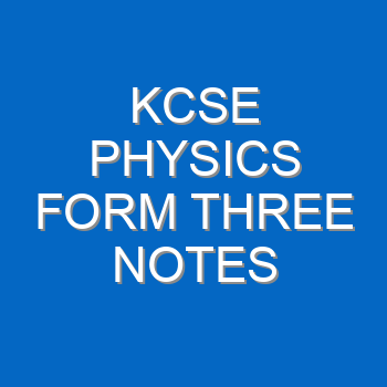
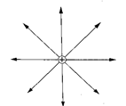
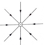
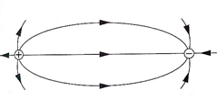
An electric field is the space around a charged body where another charged body would be acted on by a force. These fields are represented by lines of force. This line of force, also called an electric flux line, points in the direction of the force.
Electric field patterns
Just like in magnetic fields, the closeness of the electric field lines of force measures the field strength. Their direction is always from the north or positive to the south or negative.


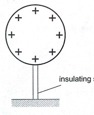
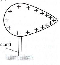
Charge distribution on conductors’ surface
A proof plane is used to determine charge distribution on spherical or pear-shaped conductors. For an isolated sphere, it is found that the effect is the same for all points on the surface, meaning that the charge is evenly distributed on all points of the spherical surface. For a pear-shaped conductor, the charge is denser in regions of large curvature (small radius). The density of charge is greatest where curvature is greatest.


Charges on or action at sharp points
A moving mass of air forms a body with sharp points. The loss of electrons by molecules (ionization) makes the molecules positively charged ions. These ions tend to move in different directions and collide, producing more charged particles, making the air highly ionized. When two positively charged bodies are placed close to each other, the air around them may cause a spark discharge, which is a rush of electrons across the ionized gap, producing heat, light, and sound in the process, which lasts for a short time. Ionization at sharp projections of isolated charged bodies may sometimes be sufficient to cause a discharge. This discharge produces a glow called corona discharge observed at night on masts of ships moving on oceans. The same glow is observed on the trailing edges of aircraft. This glow in aircraft and ships is called St. Elmo’s fire. Aircraft are fitted with ‘pig tails’ on the wings to discharge easily.
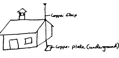
The lightning arrestors
Lightning is a huge discharge where a large amount of charge rushes to meet the opposite charge. It can occur between clouds or the cloud and the earth. Lightning may not be prevented, but protection from its destruction may be done through arrestors. An arrestor consists of a thick copper strip fixed to the outside wall of a building with sharp spikes.
Capacitors and capacitance
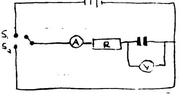
A capacitor is a device used for storing charge. It consists of two or more plates separated by either a vacuum or air. The insulating material is called ‘dielectric’. They are symbolized as shown below,
Capacitance C = Q / V where Q is charge and V is voltage.
The units for capacitance are coulombs per volt (Coul/volt) and are called farads.
1 Coul/volt = 1 farad (F)
1 µF = 10-6 F and 1 pF = 10-12 F
Types of capacitors are:
- Paper capacitors
- Electrolyte capacitors
- Variable capacitors
- Plastic capacitors
- Ceramic capacitors
- Mica capacitors
Factors affecting the capacitance of a parallel-plate capacitor
- Distance between the plates: Reducing separation increases capacitance, but the plates should not be very close to avoid ionization which may lead to discharge.
- Area of plate: Reduction of the effective area leads to reduction in capacitance.
- Dielectric material between plates: Different materials will produce different capacitance effects.
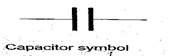
Charging and discharging a capacitor
When the switch S1 is closed, the capacitor charges through resistor R and discharges through the same resistor when switch S2 is closed.
Applications of capacitors
- Variable capacitor: Used in tuning radios to enable transmission at different frequencies.
- Paper capacitors: Used in mains supply and high voltage installations.
- Electrolytic capacitors: Used in transistor circuits where large capacitance values are required.
Other capacitors are used in reducing sparking as a car is ignited, smoothing rectified current, and increasing efficiency in a.c. power transmission.
Example
A capacitor of two parallel plates separated by air has a capacitance of 15 pF. A potential difference of 24 volts is applied across the plates.
- Determine the charge on the capacitor.
- When the space is filled with mica, the capacitance increases to 250 pF. How much more charge can be put on the capacitor using a 24 V supply?
Solution
- C = Q / V then Q = VC, hence Q = (15 × 10-12) × 24 = 3.6 × 10⁻¹⁰ Coul.
- Mica C = 250 pF, Q = (250 × 10-12) × 24 = 6 × 10⁻⁹ Coul.
Additional charge = (6 × 10⁻⁹) – (3.6 × 10⁻¹⁰) = 5.64 × 10⁻⁹ Coul.
Capacitor combination
- Parallel combination: For capacitors in parallel, the total capacitance is the sum of all the separate capacitances.
CT = C1 + C2 + C3 + … - Series combination: For capacitors in series, the reciprocal of the total capacitance is equal to the sum of the reciprocals of all the separate capacitances.
1 / CT = 1 / C1 + 1 / C2 + 1 / C3
For two capacitors in series, the total capacitance becomes:
CT = (C1 C2) / (C1 + C2)
Examples
- Three capacitors of capacitance 1.5 µF, 2 µF, and 3 µF are connected to a potential difference of 12 V as shown.
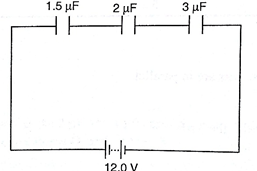
Find:
- The combined capacitance
- The charge on each capacitor
- The voltage across the 2 µF capacitor
Solution
- 1 / CT = 1 / 1.5 + 1 / 3.0 + 1 / 2.0 = 3 / 2, hence CT = 0.67 µF
- Total charge, Q = V C = 0.67 × 10-6 × 12.0 V = 8 × 10-6 = 8 µC.
- The charge is the same for each capacitor because they’re in series, hence = 8 µC.
- V = Q / C, then V = 8 µC / 2 µF = 4 V.
- Three capacitors of capacitance 3 µF, 4 µF, and 5 µF are arranged as shown. Find the effective capacitance.
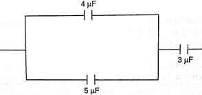
Solution
Since 4 µF and 5 µF are in parallel, then CT = 9 µF. Then the 9 µF is in series with 3 µF.
Hence CT = 27 / 12 = 2.25 µF
- Calculate the charges on the capacitors shown below.
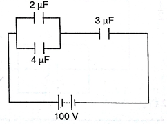
Solution
The 2 µF and 4 µF are in parallel, then combined capacitance = 6 µF.
The 6 µF is in series with the 3 µF capacitor, hence combined capacitance = 18 / 9 = 2 µF.
Total charge Q = CV then Q = (2.0 × 10-6) × 100 = 2.0 × 10⁻⁴ C.
The charge on the 3 µF capacitor is also equal to 2.0 × 10⁻⁴ C.
The p.d. across the 3 µF capacitor: V = Q / C = (2.0 × 10⁻⁴) / (3.0 × 10⁻⁶) = 66.7 V.
The p.d. across the 2 µF and 4 µF is equal to 100 V – 66.7 V = 33.3 V.
Hence Q1 = CV = 2.0 × 10-6 × 33.3 = 6.66 × 10⁻⁵ C.
Q2 = CV = 4.0 × 10-6 × 33.3 = 1.332 × 10⁻⁴ C.
N.B.
Energy stored in a capacitor is calculated as:
Work done (W) = average charge × potential difference
W = ½ QV or ½ CV2
Example
A 2 µF capacitor is charged to a potential difference of 120 V. Find the energy stored in it.
Solution
W = ½ CV2 = ½ × 2 × 10-6 × 1202 = 1.44 × 10⁻² J


