
LEARNING OBJECTIVESBy the end of this chapter, you should be able to:
|
2.1 Measurement: Measurement is essential in physics. Before any measurement is taken, the quantity to be measured and its unit must be specified.
(a) Physical Quantities of Matter
These are the measurable properties of matter, e.g., length, mass, speed, etc. They are expressed in terms of a numerical value and a unit. There are many quantities that can be measured in physics. However, some quantities are defined by using basic quantities.
(b) Basic Quantities
These are quantities of matter that are used to define other quantities of matter. The basic quantities of matter are:
- Length
- Mass
- Time
Since these quantities are used to define other units, they are referred to as fundamental quantities.
1. S.I system of Units
The S.I system of units is an International System of units based on the MKS (metre-kilogram-second) system. It is abbreviated as SI in all languages and is derived from French Le Système International d’Unités.
The basic quantities and their S.I units are shown in Table 2.1 below.
| Basic quantity | Name of Unit | Symbol of SI Unit |
|---|---|---|
| Length | Metre | m |
| Mass | Kilogram | kg |
| Time | Second | s |
Table 2.1
NB: When writing the names or symbols of the units, note that:
- Symbols of units have no plural forms. E.g., we write: 2 kg not 2 kgs
- 5 m not 5 ms
(d) Prefixes
A prefix is a word or letter placed before another. Examples of prefixes are: micro (μ), milli (m), centi (c), deci (d), kilo (k), mega (M), giga (G), and tera (T).
Prefixes can be used with the units for measuring quantities. For example:
- kilo with gram forming kilogram (kg),
- kilo with meter forming kilometer (km),
- milli with meter forming millimeter (mm),
- kilo with byte forming kilobyte (kB),
- mega with byte forming megabyte (MB),
- giga with byte forming gigabyte (GB), etc.
(e) Multiples and Sub-multiples
Multiples and sub-multiples are shown in Tables 2.2 and 2.3 below.
| Multiples | Prefix | Symbol | Sub-multiples | Prefix | Symbol | |
|---|---|---|---|---|---|---|
| 103 | Kilo | k | 10-3 | milli | m | |
| 106 | Mega | M | 10-6 | micro | μ | |
| 109 | Giga | G | 10-9 | nano | n | |
| 1012 | Tera | T | 10-12 | pico | p |
Table 2.2 Multiples Table 2.3 Sub-multiples
2.11 Instruments used for measurement
The devices used for measuring quantities are called instruments. Those used to measure the basic quantities are given in Table 2.4 below.
| Basic quantity | Instruments |
|---|---|
| Length | – Metre rule, Tape measure, Vernier calipers, and Micrometer screw gauge |
| Mass | – Electronic balance, Beam balance, Spring balance, and Triple balance |
| Time | – Stopwatch and Watch |
Table 2.4 Instruments for measuring the basic quantities of matter
2.12 Measurement of Length
Length is measured by using the Tape measure, Metre rule, Vernier calipers, and the Micrometer screw gauge.
The choice of the instrument to be used depends on:
- The size of the distance to be measured (how long or short the distance is)
- The accuracy to which the measurement is needed
(i) Measurement of Long distance
Long distances are measured using the metre rule and the tape measure. Both instruments are calibrated (graduated) in metres (m), centimeters (cm), and millimeters (mm).
1 m = 100 cm and 1 cm = 10 mm
1 m = 100 x 10 = 1,000 mm
The larger unit is kilometer (km). 1 km = 1,000 m
Note: Due to wear at the edges, when using the metre rule, it is advisable to start measuring from the 10 cm mark and deduct 10 cm from the total measurement.
(ii) Measurement of Small and very small distances
For small distances, the Vernier calipers or the engineer’s calipers are used. For very small distances such as the diameter of copper wire or thickness of paper, the micrometer screw gauge is used. Both the Vernier calipers and the micrometer screw gauge give readings with reasonable accuracy.
The Vernier Caliper
A caliper is a mechanical device used to determine small lengths with reasonable accuracy.
Types of Vernier Calipers
There are two types of Vernier Calipers:
- Simple caliper (commonly called Engineer’s caliper)
- Complex vernier
(i) Simple caliper
Simple calipers have two movable parts/legs of some desired shape and length to meet the surfaces whose separation is to be measured. The adjusted width between the leg tips is then placed against some length scale, e.g., metre rule, and the reading taken.
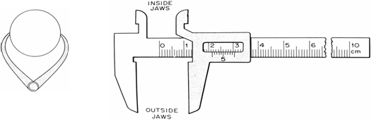
Figure 2.1 Engineer’s caliper Figure 2.2 The mechanical Vernier calipers
For measuring the internal diameter of a pipe, the caliper is turned the other way round. This way, the tips of the jaws point outward.
(ii) Complex vernier
 The more complex vernier caliper has two types of scale that allow direct reading of the adjusted width between the jaws. The types of the complex vernier are mechanical and digital. Figure 2.2 below shows the mechanical vernier.
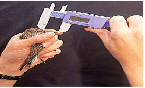
Figure 2.3 Showing a digital vernier being used to measure length of a bird
How to use the Vernier calipers
The movable jaw is adjusted until it grips the object to be measured and then the reading is taken as described below.
How to read the Vernier
(i) The Digital Vernier calipers
Once the vernier is adjusted to the width of the object to be measured, a reading is taken directly from a small screen engraved on it.
E.g., in figure 2.3, the length of the bird’s beak is 2.20 cm.
(ii) The Mechanical Vernier
For the mechanical vernier, the reading is taken in three steps:
Step I Read and record the main scale reading at the zero mark of the vernier scale to an accuracy of one millimeter.
E.g., 2.1 cm.
Step II Read and record the vernier scale reading at the position on the vernier where a mark on it coincides with a mark (division) on the main scale in tenths of millimeters.
E.g., let the 6th vernier division coincide with a mark on the main scale. In tenths, 6 becomes  = 0.6 mm = 0.06 cm
Step III Get the sum of the two readings (i.e., add the main scale reading and the vernier scale reading to get the total reading).
Main scale reading = 2.10 cm
Vernier scale reading = + 0.06 cm
Total reading = 2.16 cm
Example 1
The S.1 students of TLA measured the thickness of a desktop during physics lesson and found that the main scale reading before the zero mark of the vernier scale was 4.4 cm. Find the thickness of the desktop if the 4th vernier mark coincides with one of the marks on the main scale.
Solution Main scale reading = 4.40 cm
Vernier scale reading 4th =  = 0.04 cm
Total reading = 4.44 cm
Note: Instead of dividing the vernier reading by 10 to get the answer in mm and then by 10 to change to cm, we can divide the value directly by 100 to get the answer once in cm.
Example 2
Find the readings of the verniers shown in figures 2.4 (i) and (ii) below.
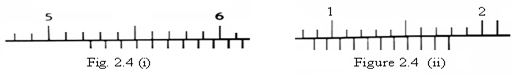
Solution:
(i) Main scale reading = 5.20 cm
Vernier scale reading 4th =  = + 0.04 cm
Total reading = 5.24 cm
(ii) Main scale reading = 0.80 cm
Vernier scale reading 8th =  = + 0.08 cm
Total reading = 0.88 cm
The Micrometer screw gauge
The Micrometer screw gauge is an instrument used to measure very small distances.
The Micrometer screw gauge is calibrated in mm on the sleeve and some small divisions on the thimble scale.
There are two types of thimble readings:
- One with 50 divisions on the thimble scale
- The other with 100 divisions on the thimble scale
However, the two types give the same reading when used to measure the same distance.
The diagram of the micrometer screw gauge is shown in Figure 2.5 below.

How to use the Micrometer screw gauge
- Place the object whose thickness is to be measured between the jaws (the anvil and the spindle) of the micrometer.
- Rotate the ratchet clockwise until the jaws touch the object. As soon as the object is gripped tight enough, it starts to slip, making a characteristic sound.
- Take the reading in three steps as shown below.
Step I: Read and record the reading on the sleeve scale at the edge of the thimble in millimeters and half millimeters. E.g., 4.0 mm.
Step II: Read and record the reading on the thimble scale opposite to the centerline on the sleeve scale (i.e., where a division on the thimble scale coincides with the centerline on the sleeve scale) in hundredths of millimeters.
E.g., Let the 33rd division coincide with the centerline.
In hundredths, 33 becomes  = 0.33 mm
Step III Get the sum of the two readings, i.e., sleeve scale reading and the thimble scale reading.
Sleeve scale reading = 4.00 mm
Thimble scale reading = + 0.33 mm
Total reading = 4.33 mm
Note: If the answer is required in cm or m, you convert it as required.
Example 1
Find the reading on the micrometer screw gauge shown in the diagrams below.

Solution (a) Sleeve scale reading = 3.00 mm
Thimble scale reading,  = + 0.29 mm
Total reading = 3.29 mm
(b) Sleeve scale reading = 7.50 mm
Thimble scale reading,  = + 0.23 mm
Total reading = 7.73 mm
SELF-CHECK 2.0
1. (a) Draw and label the diagram of the Vernier calipers.
(b) Find the thickness of a textbook measured using a vernier caliper if the main scale reading is 24 mm and the 8th vernier mark coincides with one of the marks on the main scale.
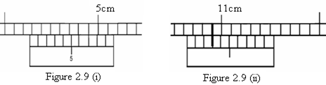
(c) Find the reading on the verniers shown in the diagrams below.
2. (a) Draw and label the diagram of the micrometer screw gauge.
(b) Find the reading on the micrometer screw gauge shown in figures 2.10 below.

2.13 Measurement of Area (Two dimensions)
Regular Surfaces
The area of regular surfaces is found by measuring any two of the following dimensions and then applying the appropriate formula.
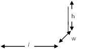
– Length (l), width (w), height (h), side (s), radius (r), and diameter
Units of area
The SI unit for area is square metre (m2).
Other units are: mm2, cm2, km2, and hectare.
1 m2 = 100 x 100 = 10,000 cm2
1 cm2 = 10 x 10 = 100 mm2
1 m2 = 1000 x 1000 = 1,000,000 mm2
Table 2.5 below shows the common regular surfaces and their respective formulae.

1. Measurement of Volume (Three dimensions)
(i) Regular Solids
The volume of regular solids is determined by measuring the dimensions and then applying an appropriate formula.
Units of Volume
The SI unit of volume is metre cubed (m3).
Other units are: mm3, cm3.
1 m3 = 1,000,000 cm3
1 cm3 = 0.000001 m3
The table below shows the common regular solids and their respective formulae.
| Figure | Name | Dimensions | Formula |
|---|---|---|---|
   A | Cylinder | r, or d & h | V = Ah or V = πr2h or V =  |
  | Cube | s | V = s3 |
 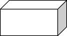
| Cuboid | l, w, h | V = lwh |
 | Sphere | r or d | V =  or orV =  |
  | Cone | r & h | V =  |

Table 2.6
(ii) Irregular Solids
The volume of irregular solids is determined by using the displacement method. In this method, the solid is fully or wholly immersed in a liquid and the volume of the liquid displaced is measured. This method operates on the principle that “A body fully or wholly immersed in a fluid (liquid) displaces its own volume“.
Apparatus/requirements used to measure the volume of irregular solids are:
(i) Measuring cylinder, water, and a piece of thin silk thread.
(ii) Measuring cylinder, overflow (displacement) can, water, and a piece of silk thread.
Measuring the volume of irregular solid
1. Using a measuring cylinder
- Fill a measuring cylinder with water.
- Read and record the initial reading.
- Tie the irregular object with a piece of thin silk thread and lower it carefully into the water in the cylinder until it is fully immersed.
- Shake it gently to remove any air bubbles.
- Read and record the final reading.
Diagram showing measurement of volume of irregular object


