SECTION A (25 marks)
Answer ALL the questions in this section in the spaces provided.
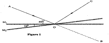
Figure 1 shows a ray of light incident on a plane mirror at O. The mirror is then rotated anticlockwise about O from position M to position M2 through an angle of 10°. The final reflected ray is OC.

Determine the angle of deviation BOC.
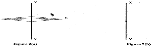
Figure 2(a) shows a magnetic compass placed under a horizontal wire XY.
A large current is passed from X to Y. Draw the final position of the magnetic compass needle in figure 3.
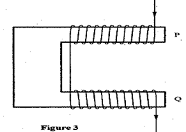
Figure 3 shows a diagram of a current-carrying wire wound on a U-shaped soft iron.
Draw the magnetic field pattern around P and Q.
A positively charged sphere is suspended by an insulating thread. A negatively charged conductor is suspended near it. The conductor is first attracted; after touching the sphere it is repelled. Explain this observation.
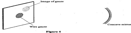
Figure 4 shows a bright electric lamp placed behind a screen which has a hole covered with a wire gauze. A concave mirror of focal length 25 cm is placed in front of the screen. The position of the mirror is adjusted until a sharp image of the gauze is formed on the screen.
Determine the distance between the mirror and the screen.
Explain why electric power is transmitted over long distances at high voltages.
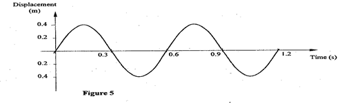
Figure 5 shows how the displacement of a point varies with time as a wave passes it.
On the same diagram, draw a wave which passes the point with half the amplitude and twice the frequency of the one shown.
A water wave of wavelength 18 mm is incident on a boundary of shallow water at right angles. If the wavelength in the shallow end is 14.4 mm, determine the refractive index of water for a wave moving from the deep to the shallow end.
The initial mass of a radioactive substance is 20 g. The substance has a half-life of 5 years. Determine the mass remaining after 20 years.
A current I flowing through a wire of resistance R was increased seven times. Determine the factor by which the rate of heat production was increased.
Figure 6 shows a horizontal conductor in a magnetic field parallel to the plane of the paper.
conductorState the direction in which the wire may be moved so that the induced current is in the direction shown by the arrow.
An x-ray tube produces soft x-rays. State the adjustment that may be made so that the tube produces hard x-rays.
The wavelength of a radio wave is 1 km. Determine its frequency. (Take the speed of light as 3.0 x 10⁸ m/s)
Figure 7 shows a block diagram of a p-n junction diode.
On the same diagram, show how a battery may be connected so that the diode is reverse biased.


 conductor


SECTION B (55 marks)
Answer ALL the questions in this section in the spaces provided.
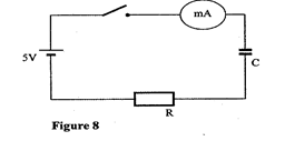
(a) Figure 8 shows a circuit that may be used to charge a capacitor.
(i) State the observation on the milliammeter when the circuit is switched on.
(ii) Explain the observation in (i) above.
(b) The circuit in figure 8 is left on for some time. State the value of p.d. across:
(i) the resistor R;
(ii) the capacitor C;
(c) Sketch the graph of potential difference (V) across R against time.
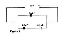
(d) Figure 9 shows three capacitors connected to a 10 V battery.
Calculate:
(i) the combined capacitance of the three capacitors;
(ii) the charge on the 5.0 μF capacitor.
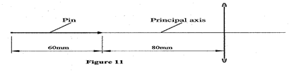
Figure 11 shows a pin 60 mm long placed along the principal axis of the lens used in part (a). The near end of the pin is 80 mm from the lens.
Determine the length of the image.
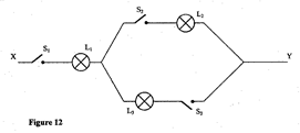
(a) Figure 12 shows an electrical circuit including three switches, S1, S2, S3, and three identical lamps L1, L2, L3. A constant potential difference is applied across X and Y.
(i) Other than L1, state the lamp that will light when S1 and S2 are closed.
(ii) How does the brightness of L1 in (i) above compare with its brightness when all the switches are closed?
(iii) Explain the observation in part (ii) above.
(b) Figure 13 shows a cell in series with a 3 Ω resistor and a switch. A high resistance voltmeter is connected across the cell.
The voltmeter reads 1.5 V with the switch open and 1.2 V with the switch closed.
(i) State the electromotive force of the cell.
(ii) Determine the current through the 3 Ω resistor when the switch is closed.
(iii) Determine the internal resistance of the cell.
(c)(i) Another resistor R is connected in series with the 3 Ω resistor so that a current of 0.15 A flows when the switch is closed. Determine the resistance of R.
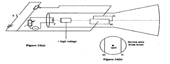
Figure 14a is a diagram of a cathode ray tube. M and N are parallel vertical plates.
(a) When switch S is open, a spot is seen at the centre of the screen as shown in figure 14(b).
(i) State what happens to the spot when S is closed.
(ii) State what would happen to the spot if the potential difference across MN is increased.
(iii) State what would be seen on the screen if the battery is replaced with an alternating emf of:
(I) a low frequency of about 1 Hz;
(II) a high frequency of about 50 Hz.
(b) Explain the process by which electrons are produced at F.
(c) State with a reason how the brightness of the spot can be increased.
(d) The accelerating voltage of the tube is 1000 V and the electron current in the beam is 1.5 mA. Determine the energy conveyed to the screen per second.
(a) State the property of radiation that determines the number of electrons emitted when radiation falls on a metal surface.
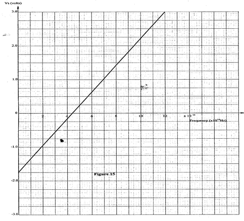
(b) Figure 15 is a graph of the stopping potential Vs against frequency in an experiment on the photoelectric effect.
(i) What is meant by stopping potential?
(ii) Given that the stopping potential Vs is related to the frequency by the equation:
Vs = (h/e)f – (w0/e), where e is the charge of an electron (e = 1.6 x 10⁻¹⁹ C)
Determine from the graph:
(I) Planck’s constant, h;
(II) the work function w0 for the metal in electron volts (eV).


PHYSICS P 1 2011
QUESTIONS AND MARKING SCHEMES
SECTION A (25 marks)
Answer all the questions in this section in the spaces provided.
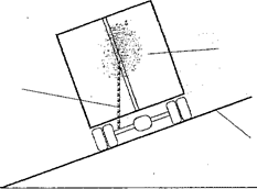
Figure 1 shows a lorry moving on an inclined section of a straight road. At the back is a chain hanging from a point on a horizontal axis through the centre of gravity of the lorry.
Lorry
Chain
Inclined road
Figure 1
(1 mark)
State with a reason whether the lorry is stable or not stable.
Stable – center of gravity is within base of lorry or
Line of action of weight is within the base
State the constant force that opposes the motion of a stone initially at rest, as it falls through air from a tall building. (1 mark)
Upthrust
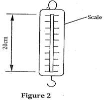
Figure 2 shows a spring balance. Its spring constant is 125 N/m. The scale spreads over a distance of 20 cm.
Determine the maximum weight that can be measured using this spring. (3 marks)
F = k e or F = k e
= 125 x 0.2 = 25 N
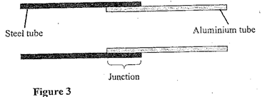
Figure 3 shows an aluminum tube tightly stuck in a steel tube.
Explain how the two tubes can be separated by applying a temperature change at the junction given that aluminium expands more than steel for the same temperature rise.
Cooling / reduced temperature
Aluminium contracts more / faster than steel
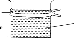
Figure 4 shows two identical beakers P and Q full of water at 90°C. Two similar cold wet clothes are wrapped, one around the top of P and the other around the bottom of Q.
Cold wet cloth
Cold wet cloth
Water
Figure 4
State with a reason the beaker in which the water cools faster. (2 marks)
P – cool layers from top descend and are replaced by hot layers or
There is complete convection currents in P
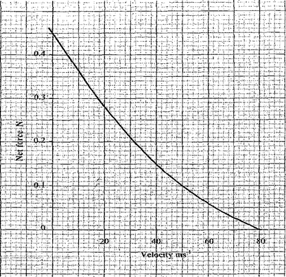
Figure 5 is a graph of net force on a body against its velocity as it falls through a liquid.
Determine the terminal velocity of the body. (1 mark)
80 m/s
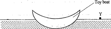
Figure 6 shows a small toy boat floating on water in a basin. X and Y are two points near the toy.
X
Water
Figure 6
When a hot metal rod is dipped into the water at point X, the toy is observed to move towards Y. Explain this observation. (2 marks)
Surface tension at X is reduced / weakened / broken
Higher surface tension at Y pulls the boat.
When the temperature of a gas in a closed container is raised, the pressure of the gas increases. Explain how the molecules of the gas cause the increase in pressure. (2 marks)
– Speed of molecules increases / kinetic energy increases / molecules move faster
– Molecules hit walls more frequently / with greater momentum / more collisions per unit time
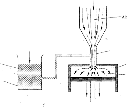
Figure 7 shows part of a petrol engine, in which air flowing under atmospheric pressure passes into a constriction, where it mixes with petrol. The mixture then flows into a combustion cylinder.
Explain what causes the petrol to move from the petrol chamber to the air stream in the constriction when the piston is moved downwards. (2 marks)
Air speed / velocity is higher at contraction
Pressure drops, higher pressure pushes the petrol
State the reason why it is easier to separate water into drops than to separate a solid into smaller pieces. (1 mark)
Smaller / weaker intermolecular forces in liquids than solids or
Smaller cohesive forces in liquids than in solids
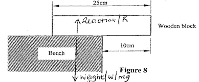
Figure 8 shows a uniform wooden block of mass 2 kg and length 25 cm lying on a bench. It hangs over the edge of the bench by 10 cm. Use the figure to answer questions 11 and 12.
11. Indicate on the figure two forces acting on the wooden block.
12. Determine the minimum force that can be applied on the wooden block to make it turn about the edge of the bench. (2 marks)
Sum of clockwise moments = sum of anticlockwise moments
or F1d1 = F2d2
20 x 2.5 = F x 10 or F x 15 = 20 x 2.5
F = 5 N or F = 3.33 N (must be 3 significant figures)
A particle starts from rest and accelerates uniformly in a straight line. After 3 seconds it is 9 m from the starting point. Determine the acceleration of the particle. (3 marks)
S = ut + ½ at2 or v = u + at or S = ½ (u + v) t
9 = 0 + ½ x a x 32
v = 3a
9 = ½ x 3v
v = 6 m/s
a = 2 m/s2
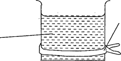
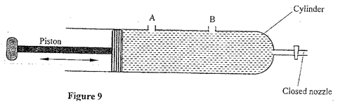
Figure 9 shows a syringe full of water. It has two identical holes A and B drilled along its cylinder. The cylinder nozzle is closed.
State with a reason how the speeds of the jets of water from A and B compare when the piston is pushed into the cylinder.
Identical jets / same speed
Pressure at same level is equal / pressure is transmitted equally throughout the liquid

SECTION B: (55 marks)
Answer all questions in this section
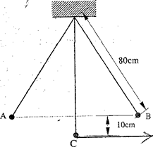
Figure 10 shows a simple pendulum of length 80 cm. The pendulum bob whose mass is 50 g oscillates between points A and B, through its rest position C. A and B are both 10 cm higher than C.
Figure 10
(a) (i) Indicate with an arrow, on the path ACB, the direction of the greatest velocity of the bob as it moves from A to B. (1 mark)
(ii) State the form of energy possessed by the pendulum bob at point A. (1 mark)
Potential energy / P.E.
(b) Determine: (3 marks)
- the velocity of the bob at point C
- the tension in the string as the bob passes point C (take acceleration due to gravity g = 10 m/s2)
T = mv2/R + mg
= 0.005 x 2 + 0.005 x 10 = 0.0625 N
(c) After some time, the pendulum comes to rest at point C. State what happens to the energy it initially possessed. (1 mark)
Used to do work against air resistance / viscous drag / air friction or converted to heat energy
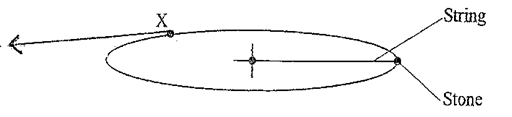
Figure 11 shows a stone attached to the end of a string moving in a horizontal circle with a uniform speed of 2 m/s. When the stone reaches point X on the circle, the string breaks.
Figure 11
(i) Indicate on the diagram with an arrow, the direction of the motion of the stone when the string breaks. (1 mark)
(ii) State the magnitude of the velocity after the string breaks. (1 mark)
2 m/s
(iii) Give a reason for your answers in (i) and (ii). (1 mark)
Obeys Newton’s first law of motion / due to its inertia / no external force acts on it / centripetal force is zero (does not act on it)
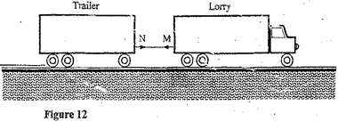
Figure 12 shows a lorry towing a trailer using a rope.
The lorry exerts a force N on the trailer and the trailer exerts an equal but opposite force M on the lorry. The frictional force between the trailer and the road is F.
Explain how the forces N, M and F enable the trailer to move. (2 marks)
N > F
M does not act on the trailer
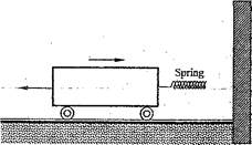
Figure 13 shows a frictionless trolley of mass 2 kg moving with uniform velocity towards a wall. At the front of the trolley is a spring whose spring constant is 25 N/m. The trolley comes to rest momentarily after compressing the spring by 3 cm and then rebounds from the wall.
Figure 13
- Determine:
(I) the force exerted on the wall by the spring. (3 marks)
F = k e
= 25 x 0.03 = 0.75 N
(II) the maximum acceleration of the trolley as it rebounds from the wall. (3 marks)
F = ma
0.75 = 2a
a = 0.375 m/s2
- State the reason why the trolley acquires a constant velocity after it rebounds. (2 marks)
Force from the spring decreases as it recovers its original length
No force on the trolley after contact with wall is lost
(a) When the temperature of water reaches the boiling point, bubbles rise to the surface.
(i) State what is contained in the bubbles. (1 mark)
Water vapour / steam
(ii) State the reason why bubbles rise to the surface only at the boiling point. (1 mark)
Vapour pressure at boiling point exceeds prevailing / external pressure
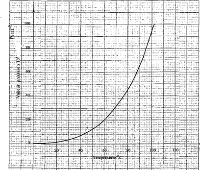
(b) Figure 14 shows a graph of vapour pressure against the temperature of water vapour, in a laboratory where a mercury barometer indicates a height of 61.8 cm.
Figure 14
(i) Determine the atmospheric pressure in the laboratory in N/m2. (Take g = 10 m/s2 and density of mercury = 13600 kg/m3). (3 marks)
P = ρgh
= 13600 x 10 x 0.618 = 84040 N/m2
(ii) Use the graph to determine the boiling point of water in the laboratory. (1 mark)
Reading of boiling point at p = 84 x 103 is 96 ± 1°C
(c) In an experiment to determine the specific heat capacity of a metal, 100 g of the metal was transferred from boiling water to a lagged copper calorimeter containing cold water. The water was stirred and a final steady temperature was realized. The following data was recorded:
- Initial temperature of cold water and calorimeter = 20°C.
- Temperature of boiling water = 99°C.
- Final temperature of water, calorimeter and the metal = 27.7°C.
- Mass of cold water and calorimeter = 130 g.
- Mass of calorimeter = 50 g.
- (Take specific heat capacity of water as 4200 J/kg/K and specific heat capacity of copper as 400 J/kg/K).
Use the data to determine:
(i) the heat gained by the water and the calorimeter; (3 marks)
Q = Mw Cw Δθ + Mc Cc Δθ
= 0.08 x 4200 x (27.7 – 20) + 0.05 x 400 x (27.7 – 20) = 2741.2 J
(ii) the specific heat capacity of the metal. (3 marks)
Heat lost by metal = heat gained by water + calorimeter
0.1 x 71.3 x c = 2741.2
c = 2741.2 / 0.1 x 71.3 = 384.46 J/kg/K
(iii) State one possible source of error in the value of the specific heat capacity obtained in the experiment. (1 mark)
Metal cooling during transfer or metal carrying some hot water into the cold water
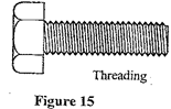
Figure 15 shows a metal bolt which is threaded.
Explain how a metre rule can be used to measure the pitch (distance between adjacent peaks) of the threading. (2 marks)
- Measure the length of the threaded part.
- Divide the length by the number of threads / pitches (divide by number of peaks – 1).
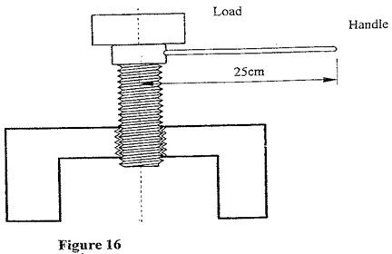
Figure 16 shows a screw jack whose screw has a pitch of 1 mm, and has a handle of 25 cm long.
Determine the velocity ratio of the jack. (3 marks)
VR = (2 π r) / pitch
= (2 x 3.142 x 0.25) / 0.001 = 1571.43
A bullet of mass 60 g travelling at 800 m/s hits a tree and penetrates a depth of 15 cm before coming to rest.
(i) Explain how the energy of the bullet changes as it penetrates the tree. (1 mark)
K.E. = heat + sound or K.E. converted to heat and sound (and light)
(ii) Determine the average retarding force on the bullet.
K.E. = work done against friction or f = ma
½ mv2 = f d
½ x 0.006 x 8002 = f x 0.15
F = 12800 N
(a) State the condition necessary for a body to float in a fluid. (1 mark)
Upthrust = weight or
Weight of fluid displaced = weight of the body or
Its density is less than that of the fluid.
(b) A ship made of steel is observed to float on water yet the density of steel is approximately eight times that of water. Explain this observation. (2 marks)
Ship has a large air space / hollow or
Average density of the ship is less than density of water
Upthrust of ship is equal to weight of the ship
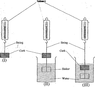
(c) Figure 17 shows three stages of an experiment to determine relative density of cork which normally floats on water. To make it sink, a sinker is hung below the cork.
In (I) a spring balance is used to measure the weight W of the cork in air.
In (II) the spring balance is used to measure the apparent weight W1, when only the sinker is submerged in water.
In (III) the spring balance is used to measure the apparent weight W2 when both the cork and the sinker are submerged.
The following observations were made:
- W = 0.08 N
- W1 = 0.060 N
- W2 = 0.28 N
Use this information to determine the:
(i) upthrust on cork. (3 marks)
Upthrust = W1 – W2 = 0.60 – 0.28 = 0.32 N
(ii) relative density of cork. (3 marks)
RD = weight of substance / weight of equal volume upthrust
= 0.08 / 0.32 = 0.25
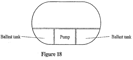
Figure 18 shows parts of a simple submarine, a ship that can travel both on water and under water. To do this water is pumped in or out of the ballast tanks.
Explain how the tanks are used to change the depth of the submarine. (2 marks)
To sink, water is allowed into ballast tanks
To float, pumps are used to expel water from ballast tanks