

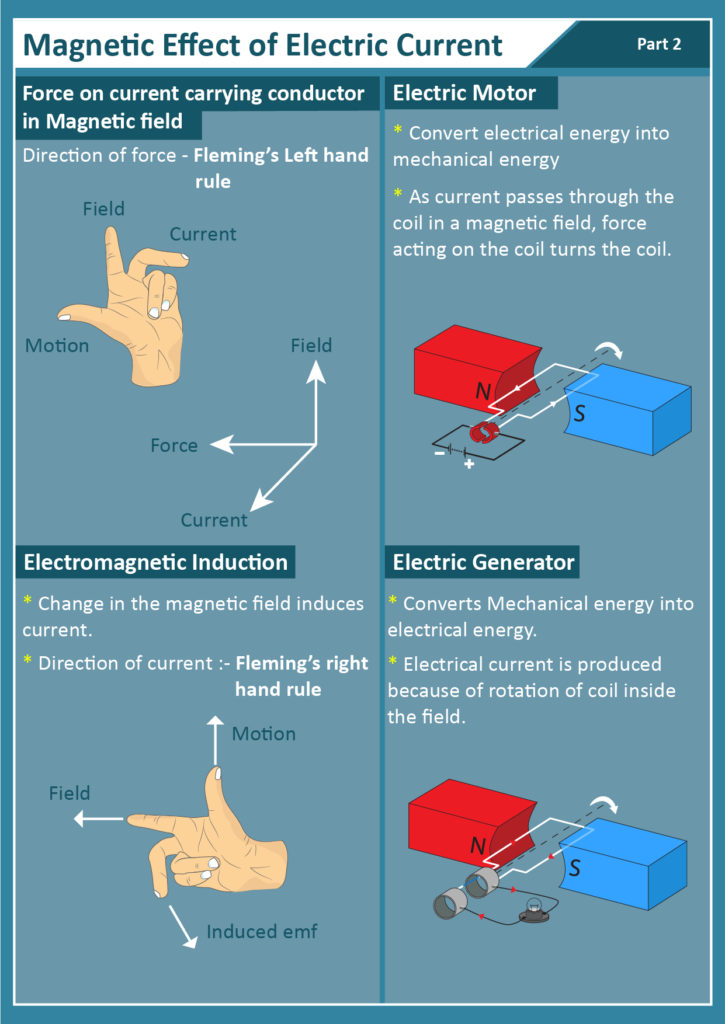
DEFINITION:
Electromagnetism is the effect produced by the interaction of an electric
current with a magnetic field.
Direction of current and magnetic field
Direction is governing by . [i]Right hand grip rule [ii]Maxwell’s right hand screw rule
Right Hand Grip Rule
It concerning the direction of current and magnetic field in a conductor and direction of current and magnetic north pole in solenoid
For solenoid
The law for solenoid states that
“Wrapping right hand around a solenoid your fingers point the direction of current and the thumb point direction of magnetic north pole”
Diagram
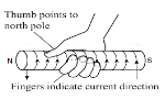
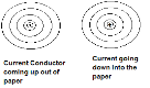
For conductor
The law for conduct States that
“Wrapping right hand around a conductor your fingers point the direction of magnetic and the thumb point direction of current”
Diagram
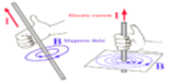
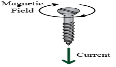
Maxwell’s Right Hand Screw Rule
The law States that
“When screw rotate advanced it moves in the direction of current and rotate in the direction of magnetic field”
Diagram:
Fleming’s Left Hand Rule
It describe the direction of force produced by conductor carrying current, which state that
“The right hand is held with the thumb, first finger and second finger of left hand mutually perpendicular to each, The Thumb represents the direction of force/Motion of the conductor, The First finger represents the direction of the magnetic Field and the Second finger represents the the direction of the current”
Diagram
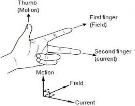
Where
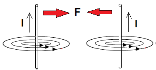
Force in Parallel Conductor
When the current pass through a two conductors in the same direction the conductors are attracted to each other
Diagram:
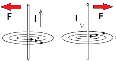
When the current pass through a two conductors in the opposite direction the conductors are repulsed to each other
Diagram:
Electromagnetic Induction
Defn: Electromagnetic induction is the production of electromotive force whenever there is change in the magnetic flux (lines) linking a conductor
Or
Defn: Electromagnetic induction is the production of an electromotive force across a conductor when it is exposed to a varying magnetic field
Diagram:
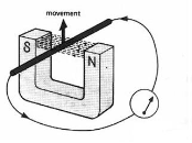
NB:
i. Magnetic flux is the line
ii. Electromotive produced is called induced electromotive force
iii. Current produced is called induced current
iv. The conductor should moves in perpendicular to magnetic field
v. No current when conductor moves parallel to magnetic field
Laws Of Electromagnetic Induction
We have two laws associated with electromagnetic induction include
i. Lenz’s law
ii. Faraday’s law
Lenz’s Law
It describe the direction of induced e.m.f, which state that
“The direction of induced e.m.f is such that the resulting induced current flows in such a direction that oppose the change that cause it”
NB:
i. When North Pole approach and South Pole withdrawing the current moves in the same direction
Diagram
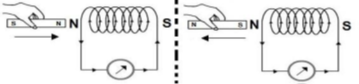
ii. When North Pole withdrawing and South Pole approach the current moves in the same direction
Diagram 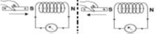
i. Faraday’s first law
ii. Faraday’s second law
Faraday’s First Law
It state that
“Whenever there is change in magnetic flux linked with a closed circuit e.m.f induced”
Faraday’s Second Law
It describe the magnitude of induced e.m.f, which state that
“The induced e.m.f in a conductor in a magnetic field is directly proportional to the rate of change of the magnetic flux linking the conductor”
Nb:
Faraday’s law can be combined and states as one as follows
“Whenever there is change in magnetic flux linked with a closed circuit e.m.f induced whose magnitude is directly proportional to the rate of change of the magnetic flux linking the conductor”
Factor Affects Induced E.M.F Magnitude
Magnitude of Induced e.m.f depend on the follows factors
i. The strength of magnetic field
ii. The rate of change of magnetic flux (speed of motion)
iii. Cross section Area of the conductor
iv. Number of turns (N)
The Strength of Magnetic Field
In electromagnetic induction, when strong magnetic it resulting high strength of magnetic field which induced high magnitude of induced e.m.f
The Rate of Change of Magnetic Flux
Number of Turns (N)
Increase in Number of turns results high magnitude of induced e.m.f
Self-Induction
Defn: Self-induction is the phenomenon in which a change in electric current in a coil produces an induced e.m.f in the coil itself
Or
Defn: self-induction is the production of e.m.f in a conductor/solenoid as a result of varies current in the same conductor/solenoid
NB:
i. If current increased results increase in induced current (back e.m.f) which subtract the original current result the resultant current be smaller than original current
Diagram:
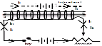
From Ohm’s law of complete circuit
E = I(R + r)
I = E/(R + r)
But: Et = E – Eb
Then: I = (E – Eb)/(R + r)
Where:
I =current of power supply
E = E.m.f of power supply
Eb = back E.m.f produced by coil
R = external resistance Faraday’s Law
It divided into two laws of electromagnetic induction include Increase in motion (speed) result high the rate at which magnetic flux change in which produce high magnitude of induced e.m.f
Cross Section Area oftheConductor
Increase in Cross section Area of the conductor results high magnitude of induced e.m.f
220
r = internal resistance
ii. If current decreased results decrease in induced current (back e.m.f) which add to the original current result the resultant current be larger than original current
Diagram:
From Ohm’s law of complete circuit
E = I(R + r)
I = E/(R + r)
But: Et = E + Eb
Then: I = (E + Eb)/(R + r)
Where:
I =current of power supply
E = E.m.f of power supply
Eb = back E.m.f produced by coil
R = external resistance
r = internal resistance
iii. In constant current no induced current
Diagram:
iv. Back e.m.f is the voltage induced
in the coil
due to variation of electric current flowing in the same coil
v. Self-induction can be minimized by using non-inductive coil
Non-Inductive coil
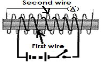
Defn: non-inductive coil is a doubly wounded turns of wires
Diagram
How Minimized Self Induction
If the electric current flowing through the first coil wire, the second coil wire cancels out by induce in the opposite direction the electric current which deflected by ammeter or galvanometer thus self-induction minimized
Mutual Induction
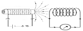
Defn: mutual induction is the production of e.m.f in one conductor or solenoid as a result of changing current in another conductor or solenoid
Diagram
NB:
i. The coil or solenoid with vary current is called primary coil
ii. The coil or solenoid with induced current is called secondary coil
Mechanism
Primary coil produces magnetic flux which change magnetic flux in secondary coil to produce electromotive force
Eddy Current
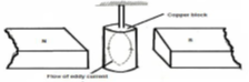
Defn: Eddy current Are induced current loops circulating within a conductor
Diagram
Damping of Eddy Current
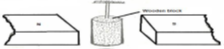
Eddy current can be minimized by insulator materials in which have high resistance in which eddy current cannot make loops circulation within a conductor
Diagram:
Methods Used To Minimize Eddy Current
Therefore Eddy current can be minimized by the following methods
i. Laminated core: this is reasons why all instrument uses principle of electromagnetic limited like motor armature, dynamos armature, transformer coil wrapped by insulator sheet
ii. Magnetic material with high resistivity e.g. ferrite
Advantage Of Eddy Current
i. Useful in heating metals
ii. Useful in electrical damping
iii. Crack detection
iv. Measurement of material thickness
v. Measurement of coating thickness
vi. Measurement of conductivity
Electric Bell
Consider the diagram below
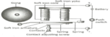
Mechanism
Induced magnetism on soft iron attract iron the armature vibrates and hammer attached to it strikes the gong which open the circuit which incomplete the circuit by contacts cause soft iron to lost magnetism where spring pullback to platinum contacts to complete circuit. This cycle of events is repeated automatically
Induction Coil
Defn: induction coil is an electrical device consisting of two coils (primary and secondary coil) where secondary coil wound over primary coil on an iron core. Also called spark coil
Diagram:
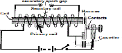
NB:
i. It used to produce high voltage alternating current (a.c) from low voltage direct current (d.c)
ii. Primary coil is made by tens or hundreds of turns of coarse wire
iii. secondary coil is made by thousands of turns of fine wire
iv. secondary coil is wound top of primary coil
v. due to large number of secondary coil very large induced e.m.f about hundreds of kilovolts (KV) is produced
vi. due to change of current caused by platinum contacts in primary coil very large induced e.m.f about hundreds of kilovolts (KV)is produced
vii. Capacitor is in parallel with the make-and-break contacts
viii. If capacitor not introduced, the secondary voltage is much less and sparking occurs between the platinum contacts
Mechanism
When switch closed to complete the circuit, the primary coil produce magnetic field (magnetism on soft iron) which cause secondary to induce high voltage due to large number of turns, Induced magnetism on soft iron attract iron hammer which open the circuit which incomplete the circuit by open the gap in platinum contacts cause soft iron to lost magnetism where spring pullback to platinum contacts to complete circuit. This cycle of events is repeated automatically
Application of Induction Coil
i. it used in ignition system of internal combustion engines
ii. a smaller version of it is used to trigger the flash tubes used in cameras and strobe lights
iii. it also used in wireless telegraphy
Moving Coil Galvanometer
It consists of a rectangular coil over soft iron cylindrical core such that are free to rotates about a vertical axis which suspended by spring which provide a restoring couple/force, the point which connected to soft iron cylindrical core and powerful permanent magnet which calved spherical poles N and S
Diagram:
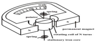
Mechanism
i. When the current pass through a coil the soft iron magnetized which may repel or attracted by permanent magnet results turning effect on the coil
ii. The turning effect is linear scale over which the pointer moves
Nb:
i. The galvanometer whose scale graduated to measure current in mill amperes is called millimeter
ii. Galvanometer can measure small current i.e. in the order of mill amperes. This is caused by the low resistance of a coil
iii. It measure only directly current
Characteristics of Highly Sensitive Galvanometer
i. Magnetic flux density (B) must be large
ii. Number of turn (N) must be large
iii. Area of coil (A) must be large
iv. Tensional constant (C) must be small
Factors Affect Galvanometer
Sensitivity
i. Magnetic flux density (B) must be large or magnetic strength
ii. Number of turn (N) must be large
iii. Area of coil (A) must be large
iv. Tensional constant (C) must be small or power of hair spring
v. Magnetic strength
The stronger magnetic used, the higher sensitivity and vice versa
vi. Number of turn
Increase the Number of turn the higher sensitivity and vice versa
vii. Area of coil (A) must be large
The large the area of coil the higher sensitivity and vice versa
viii. Power of hair spring
The less powerfully of a hair spring, the higher sensitivity and vice versa
Moving Coil Ammeter
Ammeter is device which measure current in amperes. It constructed by modification of moving coil galvanometer by connecting a low resistance called shunt parallel to the coil of galvanometer in order to measure current in amperes. Note: Rc>Rs
Diagram:
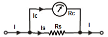
Mechanism
When the large current is passed a small current is flows through the galvanometer coil (Rc) where the rest current flows through shunt (RS)
Mathematically
i. Potential difference across galvanometer coil and shunt are equal (Vc = Vs = V)
But: V = IR
Vc = Vs
Ic x Rc = Is x Rs
ii. Since they parallel to each other, I = Is + Ic
Example,
Suppose the galvanometer coil, Rc = 10Ω and the full scale deflection current, Ic = 15mA. If it is to be converted so that it gives a full scale deflection current, I = 1.5A. Find the value of shunt
Data given
Galvanometer coil, Rc = 10Ω
Coil current, Ic = 15mA = 0.015A
Total current, I = 1.5A
Ic x Rc = Is x Rs – make Rs subject
Rs = (Ic x Rc)/Is
Rs = (0.015 x 10)/1.485
Rs = 0.15/1.485
Rs = 0.10Ω
Moving Coil Voltmeter
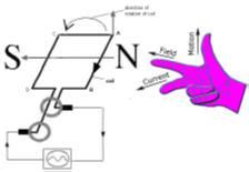
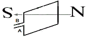
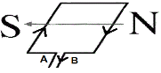
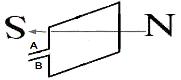
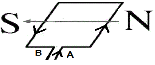
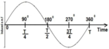
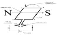
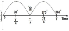
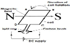
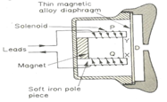
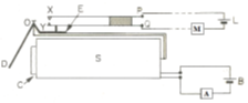
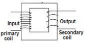
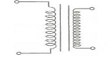
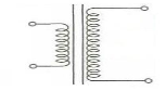
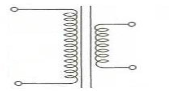
It constructed by modification of moving coil galvanometer by connecting a high resistance called multiplier series to the galvanometer coil in order to measure potential difference in volts. Note: Rc Diagram: Mechanism When the voltage (V) is passed, a small voltage is flows through the multipliers (Vm) where the rest current flows through galvanometer coil (Vc) Mathematically i. current across galvanometer coil and multiplier are equal (Ic = Im = I) But: I = V/R Vm/Rm = Vc/Rc Vm x Rc = Vc x Rm ii. Since they series to each other, V = Vm + Vc Example, Suppose the galvanometer coil resistance is 10Ω, the full scale deflection current is 15mA and the instrument is to be converted to measure a full scale deflection potential difference of 3V. Calculate the resistance of multiplier Data given Galvanometer coil, Rc = 10Ω Coil current, Ic = 15mA = 0.015A Coil voltage, Vc = Ic x Rc = 10 x 0.015 = 0.15V Total voltage, V = 3V Multiplier voltage, Vm = V–Vc = 3 – 0.15 = 2.85V Multiplier resistance, Rm= ? Solution From: Ic = Is Vm x Rc = Vc x Rm– make Rm subject Rm = (Rc x Vm)/Vc Rm = (10 x 2.85)/0.15 Rm = 28.5/0.15 Rm = 190Ω Example, : NECTA 2001 QN: 6 (a) State any characteristics of a highly sensitive galvanometer (b) (i)what is eddy current? (ii) Explain two advantage of eddy current (c) Explain how a moving coil galvanometer can be converted into an ammeter and into a voltmeter Example, : NECTA 2004 QN: 10 (a) List down two (2) factors that affect the magnitude of induced e.m.f in a moving coil galvanometer (b) (i) State the laws of electromagnetic induction (ii) Explain how eddy current are produced (iii) How can eddy current minimized (c) A moving coil galvanometer of 30Ω resistance which carries a maximum current of 15mA can be converted into an ammeter i. How can the galvanometer be made to give ampere readings? ii. If the device is to give a 1.5A full scale deflection what value resistance will be required? Data given Galvanometer coil, Rc = 30Ω Coil current, Ic = 15mA = 0.015A Total current, I = 1.5A Shunt current, Is = I – Ic = 1.5 – 0.015 = 1.485A Shunt, Rs= ? Solution From: Vc = Vs Ic x Rc = Is x Rs – make Rs subject Rs = (Ic x Rc)/Is Rs = (0.015 x 30)/1.485 Rs = 0.45/1.485 Rs = 0.303Ω Generator Defn: generator is device consist a coil rotating in an external magnetic field to produce electricity Types of Generator It divided into two according to kind of current produce i. Alternating current generator ii. Direct current generator Alternating Current Generator Defn: a.c generator is device consist a coil rotating in an external magnetic field to produce alternating current. Also is called alternator Diagram: NB: i. It uses principle of faraday’s law of induction ii. Coil spinning at constant rate in magnetic field to induce oscillating e.m.f iii. Armature (part of spinning coil) made by soft iron core with wound turns of insulated wire iv. Armature revolve freely around a strong magnetic field on an axis v. Two slip rings are connected to the ends of the armature where two carbon brushes rest on it vi. The magnetic field should cut the coil Mechanism of Alternator i. When the coil vertical at 3600 or 00 no e.m.f produced due to no cutting of the magnetic field on the coil Diagram Multiplier voltage, Vm = V–Vc = 3 – 0.15 = 2.85V Multiplier resistance, Rm= ? Solution From: Ic = Is 225 ii. When the armature is rotate at 900 (parallel to magnetic field) the motion/force of coil is perpendicular to the magnetic field hence maximum e.m.f is induced (maximum positive) Diagram: iii. When the coil vertical (at 1800) no e.m.f produced due to no cutting of the magnetic field on the coil Diagram: iv. When the armature is rotate after 1800, starting from vertical position and the side of loop interchange which cause the loop of current to change v. When the armature is rotate at 2700 (parallel to magnetic field) the motion/force of coil is perpendicular to the magnetic field hence minimum e.m.f is induced (maximum negative) Diagram: automatically hence electricity is produced Diagram: NB: i. The number of cycle produce per second is called frequency of a.c ii. The induced current is called a.c current iii. The induced e.m.f is called a.c e.m.f Direct Current Generator Defn: d.c generator is device consist a coil rotating in an external magnetic field to produce direct current. Diagram: In d.c generator the slip rings in a.c generator by replacing the half commutator to prevent reverse of current. It half commutator is called commutator segment which insulated from other half commutator Mechanism of D.C Generator i. When the coil vertical no e.m.f produced due to no cutting of the magnetic field on the coil ii. When the armature is rotate at 900 (parallel to magnetic field) the motion/force of coil is perpendicular to the magnetic field hence maximum e.m.f is induced (maximum positive) iii. When the coil vertical (at 1800) no e.m.f produced due to no cutting of the magnetic field on the coil iv. When the armature is rotate after 1800 , starting from vertical position and the side of commutator segment interchange the loop which cause the loop of current remain in the same direction v. This cycle of events is repeated automatically hence electricity is produced Diagram Advantage of alternator i. Commutator are complex and costly to construct d.c generator, therefore many d.c generator are a.c generator with rectifiers Defn: Rectifiers is the device used to flow current only in one direction. We will study further in electronics ii. Transformer works on a.c current Electric Motor Defn: is an electric device used to convert electrical energy to mechanical energy Diagram Main Parts of Electric Motor i. Carbon brushes ii. Commutator split ring iii. Magnetic field iv. Rectangular coil of wire Rectangular coil of wire Rectangular coil of wire formed by winding several turns of wire on a soft iron core Magnetic field Magnetic field is the magnetic formed by two unlike poles of permanent magnet Commutator split ring It formed by divided copper ring into two equal halves. It used to reverse direction of flowing electric current through the coil by changing the contact Carbon brushes It forms connection by power supply and rectangular coil Mechanism of Electric Motor i. when the switch is closed electric current flowing horizontal coil magnetic field produced ii. interaction magnetic field bar magnet will creates magnetic couple i.e. north pole of the coil face north pole of the bar magnet while south pole of the coil face south pole of the bar magnet iii. the coupling of the magnetic field cause the coil to rotate since Like poles repel each other and unlike poles attract iv. When coil reached in vertical position (rotate at 900 ) the commutator loose contact with carbon brush but the momentum carried by the coil takes it part to the vertical position vi. When the armature is rotate after 1800 , starting from vertical position the side AD and BC change position and the side of commutator segment interchange the loop which cause the loop of current remain in the same direction vii. This cycle of events is repeated automatically hence motor rotates in the same direction Telephones Receiver (Ear-Peace) Defn: is an electric device used to convert varying electrical energy to sound energy. The purpose of ear piece is to the reverse of microphone. Microphone is the electric device used to convert sound energy to varying electrical energy Diagram: Main Parts Of Telephones Ear-Peace i. Permanent magnet ii. Insulated wire (solenoid) iii. Magnetic allow diaphragm iv. Lead wire used for connection Permanent magnet It is placed between two solenoids Solenoid It kept by insure that the same pole facing in the same direction Magnetic allow diaphragm It formed by impregnated iron fillings on a piece of paper Lead wire It used for connection from source of varying electric current to each solenoid Mechanism Of Telephones Ear-Peace i. When one speak through the microphone in one line of a telephone the sound energy is converted into electrical energy entering the ear piece of another line through lead wire ii. The sound makes a diaphragm(a kind of small tight drum skin stretched across the narrow end of the hone ) vibrates iii. The vibration move a coil near a magnet, converting the mechanical sound energy into a varying/fluctuating electric current iv. The electric current travels through lead wire v. At the receiving end similar equipment reverses the process. The electric current flows into a coil placed near a magnet, making the coil move back and forth and pushing another diaphragm vi. The diaphragm stretched over a second horn, recreates the original sound Nb: Magnetic Relay Defn: Magnetic relay is an electric device which is used to control one circuit when an electric current is flowing in the other circuit Or Magnetic relay is switch used to control large current in the secondary current when small electric current flowing in the primary circuit Main Parts of Magnetic Relay i. Solenoid ii. Contact iii. Insulating block iv. Spring v. Soft iron armature Diagram: Mechanism of Magnetic relay i. When an electric current from battery B is flowing in the solenoid S, the core C becomes magnetized and attracts iron armature lever D pivoted at O cause part E to move upward ii. This close a gap between two spring-loaded Y and X which joined tobattery L and allow electrical current to flow to the other electrical equipment Uses of Magnetic relay i It is used in telephone exchange system during dialing of numbers ii Switching on or off heavy current in most electronics devices Mechanism of Telephone exchange system i. When an electric current from battery B when dialing from telephone A in solenoid S , the core C becomes magnetized and attracts iron armature lever D pivoted at O cause part E to move upward ii. This close a gap between two spring-loaded Y and X which joined to battery L and allow electrical current to flow to the distance telephones exchange M iii. Thus a message sent by operating A is passed to M Transformer Defn: transformer is the device uses mutual induction to convert a.c voltage to large or low or Transformer is an electrical device that transfers energy between two or more circuits through electromagnetic induction. The coil connected to the source is called primary coil and the coil e.m.f induced is called secondary coil Diagram: Its symbol Types of Transformer They are two types includes i. Step up transformer ii. Step down transformer Step Up Transformer Step up transformer is the transformer used to convert from low a.c voltage to high a.c voltage Diagram NB: i. Primary coil is made by turns of coarse wire while secondary coil is made by turns of fine wires ii. Primary coil is made by less turns of coarse wire while secondary coil is made by higher turns of fine wires Step Down Transformer Step down transformer is the transformer used to convert from high a.c voltage to low a.c voltage Diagram i. Secondary coil is made by turns of fine wire while primary coil is made by turns of coarse wires ii. secondary coil is made by less turns of fine wire while primary coil is made by higher turns of coarse wires Transformer Equation From the factor affect induced e.m.f (faraday’s law) For primary coil Np α Vp– removes proportionality constant Np= K Vp- – – – – – – – 1 For primary coil Ns α Vs– remove proportionality constant Ns = K Vs – – – – – – – – 2 Divide equation 1 to equation 2 Np/Ns = (K Vp)/(K Vs) Np/Ns = Vp/Vs Suppose no loss in power Pp = Ps But: p = IV Then: Ip x Vp = Is x Vs – make Vp/Vs subject Vp/Vs = Is/Ip Therefore: Vp/Vs = Is/Ip = Np/Ns Vp/Vs = Is/Ip = Np/Ns Where: Np = number of turn in primary coil Ns = number of turn in secondary coil Vp = potential difference in primary coil Vs =potential difference in secondary coil Ip = current in primary coil Is =current in secondary coil Ps =power in secondary coil Transformer Efficiency Defn: Transformer efficiency is the ratio of secondary coil power to primary coil power express as a percentage Mathematically: Eff = (????) ? But: Ps = Is x Vs Pp = Ip x Vp Then: Eff = (Ps/Pp) x 100% Eff = (?? Eff = (Is Ip )(Vs Vp ) ? 100% But: Ns/Np = Vs/Vp Then: Eff = (Is Ip )(Ns Np ) ? 100% Eff = (?? Example, A transformer is used to step down 240V mains supply to 12V for laboratory use. If the primary coil has 600 turns, determine the number of turns in the secondary coil Data given Number of turn in primary coil, Np = 600 turns Potential difference in primary coil, Vp = 240V Potential difference in secondary coil, Vs = 12V Number of turn in secondary coil, Ns = ? Solution From: Np/Ns = Vp/Vs – make Ns subject Ns = (Vs x Np)/Vp Ns = (12 x 600)/240 Ns = 7200/240 = 30 Ns = 30 turns Example, A current of 0.6A is passed through a step up transformer with a primary coil of 200 turns. A current of 0.1A is obtained in the secondary coil. Determine the number of turns in the secondary coil and the voltage across if the primary coil is connected to 240V mains. Data given Number of turn in primary coil, Np= 200 turns Potential difference in primary coil, Vp = 240V Current in primary coil, Ip = 0.6 A Current in secondary coil, Is = 0.1A Number of turn in secondary coil, Ns = ? Potential difference in secondary coil, Vs= ? Solution Number of turn in secondary coil, Ns = ? From: Np/Ns = Is/Ip – make Ns subject Ns = (Ip x Np)/Is 230 Ns = (0.6 x 200)/0.1 Ns = 120/0.1 = 1200 Ns = 1200 turns Potential difference in secondary coil, Vs= ? From: Np/Ns = Vp/Vs – make Vs subject Vs = (Vp x Ns)/Np Vs = (240 x 1200)/200 Vs= 288000/200 = 1440 Vs = 1440V Example, A step up transformer has 10000 turns in the secondary coil and 100 turns through the primary coil. An a.c of 5A flow in the primary coil when connected to a 12V a.c supply, Calculate a) the voltage across secondary coil b) current in secondary coil if transformer efficiency is 90% Data given Number of turn in primary coil, Np= 100 turns Number of turn in secondary coil, Ns = 10000 Potential difference in primary coil, Vp = 12V Current in primary coil, Ip = 5 A Transformer efficiency, Eff = 90% Potential difference in secondary coil, Vs= ? Current in secondary coil, Is = ? Solution a) Potential difference in secondary coil, Vs= ? From: Np/Ns = Vp/Vs – make Vs subject Vs = (Vp x Ns)/Np Vs = (12 x 10000)/100 Vs = 120000/100 =1200 Vs = 1200V b) Current in secondary coil, Is = ? From: Eff=(Is x Vs Ip x Vp ) ? 100%- make Ps subject Is =Eff x Ip x Vp Vs x 100% = 90 x 5 x 12 1200 x 100% Is = 5400/120000 = 0.045 Is = 0.045A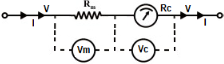
???%
?
??
??
?
? ) ?
???%
?
??
??
?
? ) ?
???%


1 Comment