


LEARNING OBJECTIVES By the end of this chapter, you should be able to: 1. Define: – Machine,
2. State: – The types of machines,
3. Carry out calculation on:
4. Sketch graphs of: – M.A against load and – η against load. 5. Explain: – The shapes of the graphs and – Why the graph for efficiency against load levels below 100%. |
8.1 Machine
Definition: A machine is a device that makes work easier for man.
The “machine” is a symbol of modern life. In machines, an effort (force) is applied to move a load. The effort can be:
- Muscular effort from man or
- Force derived from an engine.
Principle of Simple Machines
The principle used in simple machines is to produce a big force over a small distance by using a small force over a large distance. The force which we apply to the machine is known as effort (E) and the force which we have to overcome is known as load (L).
8.11 Types of machines
There are two types of machines, namely:
- Simple machines and
- Complex machines.
(a) Simple Machines
These are devices that work with one movement and change the size and direction of forces. Examples of simple machines are simple tools with one or two parts.
Although simple machines provide the advantage of using less force (effort) and thus making the work easier, they do not reduce the amount of work.
(b) Kinds of Simple Machines
There are six kinds of simple machines. They include the following:
- Lever, Pulley, Wheel and Axle, Inclined plane, Gears, Screws.
Note: The screw and the wedge are modified forms of inclined plane. So we can say that basically there are four classes of simple machines.
8.12 Levers
A lever is a rigid bar which is free to move about a fixed point known as the fulcrum or pivot. It is divided into classes.
Classes of Lever
There are three classes of levers, namely:
- the first class lever
- the second class lever
- the third class lever
(a) First Class Lever
A first class lever is the type of lever in which the fulcrum is between the effort and the load. Examples of first class levers are:
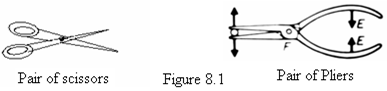
(b) Second Class Lever
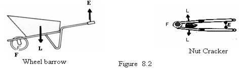
A second class lever is a lever in which the load is between the effort and the fulcrum.
A wheelbarrow, nut cracker, and a bottle opener are examples of second class levers.
(c) Third Class Lever
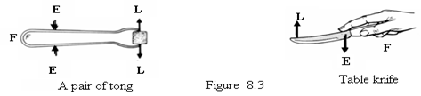
A third class lever is a lever in which the effort is between the load and fulcrum.
Examples of third class levers are:
Memory Aid
1. Edward Feels Lonely Edward Feels Lonely
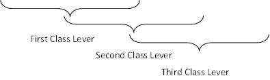
2. Use the word PLE to remember the classes of lever. When each letter is in the middle beginning from P to E, the order of the classes starts from 1st to 3rd. See summary in the table below.
Position of letter | Class of lever |
L P E | 1st |
P L E | 2nd |
P E L | 3rd |
PLE stands for Pivot, Load and Effort respectively.
8.13 Mechanical Advantage (M.A)
The relationship between the load (L) and the effort (E) acting on a simple machine is called mechanical advantage. In ideal conditions (where there is no loss in energy due to friction), mechanical advantage is defined as the ratio of the load to the effort.
Mechanical Advantage (M.A) = Load ÷ Effort
NB: Mechanical advantage has no unit because it is the ratio of the same quantity, i.e., force.
Examples
1. If a lever can be used to overcome a load of 50 N by applying an effort of 10 N, find the M.A of the lever.
Solution: L = 50 N, E = 10 N, M.A = ?
M.A = 50 ÷ 10 = 5
2. (a) A lever is used to overcome a load of 2000 N. If the M.A = 2, calculate the effort applied.
- If the same lever is used to overcome a load by applying an effort of 50 N, determine the maximum load that can be overcome.
Solution:
(a) L = 2000 N, E = ?, M.A = 2
(b) L = ?, E = 50 N, M.A = 2
M.A = L ÷ E
2 = 2000 ÷ E
2E = 2000
E = 1000 N
For (b):
L = 2 × 50 = 100 N
8.2 Pulleys
A pulley is a wheel with a grooved rim over which passes a rope or string. The effort is applied to one end of the rope, and the disk of the pulley rotates as the rope moves over it.
There may be several pulleys in a framework called a block.
Types of Pulleys
There are several types of pulleys in use. The most common ones are:
- Single fixed pulley.
- Single movable pulley.
- Block and Tackle system.
Pulleys reduce the effort to lift an object by increasing the distance over which the effort is applied.
8.21 A Single Fixed Pulley
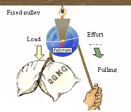 A single fixed pulley is a type of pulley fixed to a support, usually up as shown in figure 8.4. A rope passes over the groove of the pulley. One end of the rope is attached to the load, and the effort is applied at the other end.
 Common examples of a single pulley can be found at the top of a flagpole and in construction sites.
Pulling down on the rope causes the flag (load) to move upward. Thus, the pulley changes the direction of the force applied to the rope.
(a) Facts about the Single fixed pulley
- A single fixed pulley is like a first class lever because its fulcrum is between the load and the effort.
- The force arms of the pulley are equal to each other; therefore, E = L in an ideal machine. However, in practice, the effort applied to overcome the load must be greater than the load due to friction in the moving parts of the pulley.
- The tension is the same throughout the rope.
- If we pull the rope down by x m, the load rises up by the same distance, x m, and gains potential energy.
- Its diagram is always drawn as simply as in figure 8.5.
(b) To Show that for an ideal condition E = L (i.e., Neglecting friction)
Neglecting friction, in the system we have:
Work input = Work output
Work done by effort = Work done by load
Effort × Effort distance = Load × Load distance
E × x m = L × x m
E = L
(c) Mechanical Advantage (M.A) of a Single Fixed Pulley
In a single fixed pulley, the tension is the same throughout the rope. Neglecting the weight of the string and the frictional forces in the pulley, we have:
Load = Effort
M.A = Load ÷ Effort
= 1 (But L = E)
NB:
- M.A = 1 means that there is no gain in either force or distance in a fixed pulley; therefore, no mechanical advantage.
- In reality, the actual M.A is slightly less than 1 because of the friction of the rope against the pulley and the friction between the pulley and the axle on which it turns.
- The primary benefit of a single pulley is to change the direction of the force or to move a load to a point (such as the top of a flagpole) that cannot be reached by the user.
8.22 A Single Movable Pulley
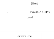
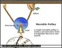


 A single movable pulley is a pulley which moves along a rope with the load attached to it. One end of the rope is tied to a fixed support and passes over the pulley, and the other end where the effort is applied goes back up to the user.
(a) Facts about a single movable pulley
- A single movable pulley reduces the amount of effort needed to lift the load, i.e., half the load is necessary to lift a given load.
- If we pull the rope up by x m, the load rises by half the effort distance (i.e., ½ x m).
- The tension in the string is equal to the effort applied, so that the total upward pull is twice the effort, i.e., 2E.
- For simplicity, its diagram is drawn as in figure 8.7.
(b) Mechanical Advantage of Single movable pulley
Let load of L N be supported by the pulley and that the weight of the pulley and the string plus the frictional force in pulley are negligible.
Since the load is supported by two sections of the string, the effort applied is equal to 2E.
Load = L N and Effort = 2E N
In equilibrium: Downward force = Upward force
L = 2E
M.A = L ÷ E = 2
Alternatively, from L = 2E, E = L ÷ 2
Substituting for L and E in M.A = L ÷ E we have;
M.A = L ÷ (L ÷ 2) = 2
NB:
- The M.A of a movable pulley (or a system of pulleys with a movable part) equals the number of strands of rope coming from the movable part (the load being lifted).
- Since a pulley system with an M.A of 2 increases the force by a factor of 2, the pulley system must also double the distance the effort travels. Therefore, in order to raise a load a given distance, the user must pull and take in twice as much rope.
Worked Example
1. An effort E is used to raise a load of 200 N. If the effort moves through a distance of 4 m, calculate: (i) the effort (ii) the M.A and (iii) the load distance.
Solution: E = ?, M.A = ?, Effort distance = ?, Load distance = 4 m, L = 200 N.
(i) In equilibrium; (ii) Mechanical Advantage,
Downward force = Upward force M.A = L ÷ E
200 = 2E
E = 100 N
(iii) Neglecting friction, in the system we have:
Work input = Work output
Effort × Effort distance = Load × Load distance
100 × 4 = 200 × Load distance
Load distance = 2 m
8.3 Block and Tackle System
A block and tackle system is a pulley system consisting of both fixed and movable pulleys.
In this system, there are two blocks; each block contains one or more pulley(s), depending on the M.A required. A single rope is used and passes over the groove of each pulley. The framework of pulleys is called block, and the rope passing over each pulley is called the tackle.
(a) Practical applications where Block and Tackle system is used
They are commonly used to raise or move loads in:
- Sailing ships.
- Cranes,
- Lifts, and
- Breakdowns.
Diagrams Showing Block and Tackle Systems
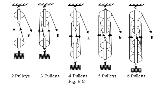
Note: (i) For an odd number of pulleys in the system, the fixed upper block contains one more than the lower block, and the string starts from the lower block.
- The number of strings supporting the lower movable block is equal to the number of pulleys in the system.
M.A of A Block And Tackle System
In a block and tackle system, an effort E is applied and creates a tension, T, in the string. The movable lower block is acted upon by n sections of the string pulling it upwards and the load, L, pulling downwards.
For equilibrium in a perfect machine,
Downward force = Upward force
L = nT but T = E
L = nE
Substituting for L in M.A = Load ÷ Effort we obtain:
M.A = L ÷ E = nE ÷ E = n
Where: n = the number of strings supporting the lower block and is also the total number of pulleys in the system.
NB:
- The more the number of pulleys in the system, the higher the M.A and the easier the work done.
- In practice, however, the M.A is always less than the number of strings supporting the lower block or less than the number of pulleys in the system.
Reason: Extra effort is required to overcome:
- Friction in the moving parts of the pulleys
- The weight of the movable pulley and the string.
(c) Velocity Ratio (V.R) or Speed Ratio
Definition: The velocity ratio of a machine is defined as the ratio of the distance moved by the effort to the distance moved by the load.
Velocity Ratio (V.R) = Distance moved by effort ÷ Distance moved by load
In any system of block and tackle, to raise the load by a distance of x m, each string supporting the load shortens by x m. The effort is therefore applied through a total distance of nx metres.
From V.R = Distance moved by effort ÷ Distance moved by load
V.R = nx ÷ x = n
The V.R of a block and tackle system = the number of strings supporting the lower block = the number of pulleys in the system.
(d) Calculations for Perfect pulley systems
Steps in problem solving
Before solving any problem, ask yourself the following questions:
- What is asked in the question?
- What information is given to help you solve the problem?
- What are the equations to solve the problem?
These questions can only be answered when you collect the data.
Example 1
A force of 10 N is required to raise a load, L, using a smooth (frictionless) and weightless block and tackle system of four pulleys. Calculate:
(a) (i) Load, (ii) M.A and (b) Effort distance if the load rises by 2 m.
Solution: E = 10 N, M.A = ?, Effort dist = ?, Load dist = 2 m, L = ?, No. of pulleys = 4
(a) (i) In equilibrium; (ii) Mechanical Advantage,
Downward force = Upward force M.A = L ÷ E
L = 4E = 4 × 10 = 40 N
M.A = 4
(iii) Neglecting friction, in the system we have:
Work input = Work output
Effort × Effort distance = Load × Load distance
10 × Effort distance = 40 × 2
Effort distance = 8 m
8.31 The Principle of Work
The Principle of Work states that:
The amount of work output is always less than the amount of work input.
(a) Efficiency (η) of a Machine
Definition: The efficiency of a machine is the ratio of work output to work input.
Efficiency is always expressed in percentage form, i.e.,
Efficiency = (Work output ÷ Work input) × 100
NB:
- Work output = Work done by the load
- Work input = Work done by the effort
(b) Relation between M.A, V.R and η
From Efficiency = (M.A ÷ V.R) × 100
Efficiency = (Mechanical Advantage ÷ Velocity Ratio) × 100
Efficiency = M.A × (1 ÷ V.R) × 100
η = (M.A ÷ V.R) × 100
NB:
- This equation is useful only for solving problems. It is not a fundamental definition for efficiency and should NOT be used as such.
- Efficiency of a machine is always less than 100%.
Reasons:
- Because of frictional forces between the moving parts of a machine.
- For the case of pulleys, other reasons are:
- The weight of the string and
- The weight of the lower movable block.
(c) Efficiency of a machine can be increased by:
- Lubricating the moving parts of the machine.
- For the case of pulleys, by making the string and the block plus the pulley(s) as light as possible.
8.32 Graphical Relations between M.A and Load and Efficiency and Load
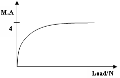
When we plot M.A or η against load, the following graphs are obtained.
The graph of M.A = n against Load The graph of η against Load

Explanation of the Shapes of the graphs
In both graphs, a small increase in load causes a high increase in M.A and η. On further increase in the load, the graphs begin to level as M.A and η approach their maximum values. At a certain value of load, the M.A and η reach their maximum values and then remain constant; hence, the graphs level.
NB: For figure (a), the graph levels at the value of the M.A. While for figure (b), the graph levels below 100% for imperfect machines and levels at 100% for perfect machines.
Worked Examples
1. (a) Define the following terms:
 (i) Mechanical advantage
(ii) Velocity ratio
(b) The diagram in the figure shows a pulley system used to raise a load.
(i) What is the velocity ratio of the system?
(ii) Find how far the load is raised if the effort moves down by 4 m.
(iii) Calculate the effort required to raise a load of 800 N, if the mechanical advantage of the system is 4.
(iv) Calculate the efficiency of the system.
(c) Explain what happens to the efficiency of the system in (b) above if the load is much:
(i) less than 800 N.
(ii) more than 800 N.
(d) Draw a sketch graph to show how mechanical advantage of the system in (b) varies with the load.
(e) Give two practical applications where pulley systems are used.
Solution:
(a) (i) Mechanical advantage is the ratio of load to effort.
(ii) Velocity ratio is the ratio of effort distance to load distance.
(b) (i) V.R = 5
(ii) Effort distance = 4 m, Load distance = ?, V.R = 5
V.R = Effort distance ÷ Load distance
5 = 4 ÷ Load distance
Load distance = 0.8 m
(iii) E = ?, L = 800 N, M.A = 4.
M.A = Load ÷ Effort
4 = 800 ÷ E
E = 200 N
(iv) η = ?, M.A = 4, V.R = 5
η = (M.A ÷ V.R) × 100 = (4 ÷ 5) × 100 = 80%
(c) (i) The efficiency is less than 80%.
(ii) The efficiency remains constant at 80%.
(d) The graph of mechanical advantage against load.
(e) They are used in cranes, breakdowns, ships, docks for lifting load.
Inclined Plane
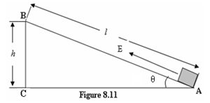 An inclined plane refers to a type of machine in which a plane is inclined at an angle to the horizontal such that one end is higher than the other. It is used to raise heavy loads by pulling/pushing them along the sloping surface. This is much easier than lifting the load through the vertical height, h, since the weight of the load acts vertically downwards.
In order to raise the load through a vertical height h, the effort, E, is applied through a longer distance, l, equal to the length of the plane, and the load is raised through a vertical height, h.
Examples of inclined planes include:
- Sloping roads
- Staircases
(a) M.A of an Inclined Plane
The M.A of an inclined plane may be obtained by assuming the machine to be perfect (i.e., neglecting the work done against friction).
Thus, Work output = Work input
Load × Distance moved by load = Effort × Distance moved by effort
Load × h = Effort × l
M.A = Load ÷ Effort = l ÷ h
But in practice M.A < l ÷ h due to friction.
(b) The V.R of the Inclined Plane
Velocity Ratio = Distance moved by effort ÷ Distance moved by load
V.R = l ÷ h
(c) The V.R of an Inclined plane in terms of angle of inclination, θ (i.e., ∠BAC)
Velocity Ratio = AB ÷ BC
V.R = l ÷ h
Using trigonometry, AB and BC are expressed in terms of Sin θ and Tan θ and then substituted in the equation.
From Sin θ = h ÷ l
AB = l = h ÷ Sin θ
And from Tan θ = h ÷ AC
BC = Tan θ × AC
Substituting these in the equation for V.R, we have:
V.R = (h ÷ Sin θ) ÷ (Tan θ × AC) = (1 ÷ Sin θ) × (1 ÷ Tan θ) = 1 ÷ (Sin θ × Tan θ)
NB: The derivation of the formula is not necessary at this level. You will understand it when you cover trigonometry in mathematics in S.2.
Example 1
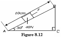 A load of 40 N is pulled steadily from A to B along an inclined plane by a force F as shown in figure 8.12. Find the velocity ratio of the system.
A 1.0 B 1.2 C 2.0 D 4.0
Answer = C
How to work it: AC = 10 cm, BC = ?, θ = 30°
BC = Tan θ × AC = Tan 30° × 10 = 0.5774 × 10 = 5.774
Using the formula V.R = l ÷ h we have:
V.R = 10 ÷ 5.774 = 2
Example 3
A wooden plank 3 m long is used to raise a load of 1200 N through a vertical height of 60 cm. If the frictional force between the load and the plane is 40 N, calculate:
(a) The effort required.
(b) The mechanical advantage.
Solution: (a)
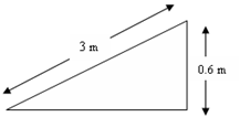
Data: L = 1200 N, E = ?, l = 3 m, h = 60 cm = 0.6 m, Frictional force = 40 N.
The effort required can be got by applying the principle of work.
Work input = Work output + Useless work done
Work done by effort = Work done by load + Work done by frictional force
E × Effort distance = Load × Load distance + Frictional force × Effort distance
E × 3 = 1200 × 0.6 + 40 × 3
3E = 720 + 120 = 840
E = 840 ÷ 3 = 280 N
(b) M.A = Load ÷ Effort = 1200 ÷ 280 = 5
8.5 Wheel and Axle
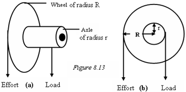 A wheel and axle is a type of simple machine made up of a wheel and axle tightly attached to each other so that they turn together about an axis. The effort is applied to the larger wheel and the load is raised by a string attached to the axle as shown in figure 8.13 below.
For one complete turn, the load and the effort move through distances equal to the circumferences of the wheel and the axle respectively.
(a) Facts about the Wheel and Axle
- A small force applied over a large distance raises a large force over a small distance.
- A wheel and axle is simply a first class lever which moves in a circle; having the fulcrum at the centre. See figure 8.13 (b).
(b) The V.R of Wheel and Axle
Velocity Ratio = Distance moved by effort ÷ Distance moved by load
= Circumference of wheel ÷ Circumference of axle
= 2πR ÷ 2πr
V.R = R ÷ r
Where R and r are the radius of the wheel and the axle respectively.
The larger the radius of the wheel, the higher the V.R and easier work done.
(c) The M.A of Wheel and Axle
The M.A of wheel and axle is obtained by taking moments of the load and effort about the axis of rotation.
Applying the principle of moments, figure 8.13 (b) we have:
Clockwise moment = Anticlockwise moment
Load × Radius of axle = Effort × Radius of the wheel
L × r = E × R
M.A = Load ÷ Effort = R ÷ r
But in practice M.A < R ÷ r due to frictional forces in the machine.
Example
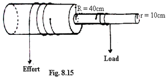 The above figure shows a wheel and axle system. When an effort of 300 N is applied, a load of 900 N is raised through a distance of 1.0 m. Calculate:
(a) The velocity ratio.
(b) The efficiency of the system.
Solution: (a) R = 40 cm, r = 10 cm, E = 300 N, L = 900 N
V.R = R ÷ r = 40 ÷ 10 = 4
(b) η = (M.A ÷ V.R) × 100 = (900 ÷ 300) ÷ 4 × 100 = (3 ÷ 4) × 100 = 75%
8.6 Gears
A gear is a device which consists of a set of toothed wheels. Gears change the direction and the speed of rotation. They are similar to wheel and axle. In gear wheels, the effort and the load are applied to the shafts connected to the gears.
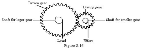
(a) Types of gears
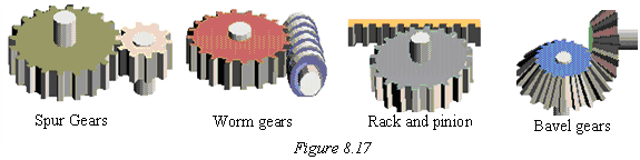
There are four types of gear systems, namely:
- Spur gears,
- Worm gear,
- Rack and Pinion, and
- Bevel gears
Figure 8.17 below shows the common types of gear systems in use.
(b) Facts about gears
- When a gear is engaged, the order of the rotation and the speed of the gears change.
- The number of rotations of gear wheels depends on the ratio of the number of teeth and radii of the wheels.
- The direction of driven gear is opposite to that of the driving gear.
- There are several gear systems as shown in figure 8.17 above. But we always consider the spur gears.
(c) The Velocity Ratio of Gears
Whichever the driving and the driven wheel is, the V.R is given by the formula:
Velocity Ratio = Number of teeth on driven gear ÷ Number of teeth on driving gear
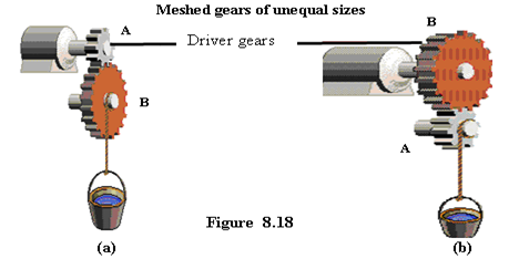
The velocity ratio of gears depends on which gear wheel the effort is applied.
Torque may be applied to the smaller gear in order to increase the torque and decrease the rate of rotation of the larger gear. Or
Torque may be applied to the larger gear in order to decrease the torque and increase the rate of rotation of the smaller gear.
Example
1. Two gear wheels A and B with 20 and 10 teeth respectively lock into each other. They are fastened on axles of equal diameters such that a weight of 100 N attached to a string wound around one axle raises a load of 160 N attached to a string wound around the other axle. Calculate:
- the velocity ratio.
- the efficiency of the system, for figure 8.18 (a).
(b) (i) the velocity ratio.
- the efficiency of the system, for figure 8.18 (b).
Solution: No. of teeth of driving wheel, A = 10, No. of teeth of driven wheel, B = 20, E = 100 N, L = 160 N
(a) (i) V.R = Number of teeth on driven gear ÷ Number of teeth on driving gear = 20 ÷ 10 = 2
(ii) η = (M.A ÷ V.R) × 100 = (160 ÷ 100) ÷ 2 × 100 = (1.6 ÷ 2) × 100 = 80%
(b) (i) V.R = 10 ÷ 20 = 0.5
(ii) η = (M.A ÷ V.R) × 100 = (160 ÷ 100) ÷ 0.5 × 100 = (1.6 ÷ 0.5) × 100 = 320%
8.7 The Screw
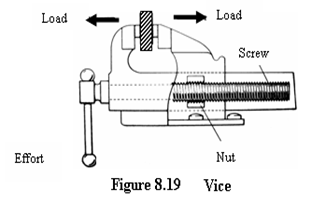 The screw is a slope turning around a pole. It is like a spiral staircase. Like a load moving up or down an inclined plane under the effect of an effort, a screw goes in or comes out of a bolt or wood. It is an essential feature of machines such as the vice and the car screw jack. The distance between any two successive threads on a screw is called pitch. Normally the vice and the car jack have handles to which effort, E, is applied. When we turn the screw, it changes the direction of the effort. For a complete turn, the load, L, moves a distance equal to the pitch.
(a) M.A of the screw
The M.A is obtained by assuming the system to be perfect, i.e., ignoring frictional forces.
Thus, Work done by effort, E = Work done by load, L
Effort × Distance moved by effort = Load × Distance moved by the load
E × (2πr) = L × pitch
M.A = Load ÷ Effort = (2πr) ÷ pitch
(b) The V.R of screw
The V.R of the screw is given by the formula:
Velocity Ratio (V.R) = Distance moved by effort ÷ Distance moved by load
V.R = (2πr) ÷ pitch
Note that: Since the screw is assumed to be perfect, M.A = V.R.
Worked Examples
1. (a) In a screw jack the length of handle is 24 cm and the screw pitch is 2 mm. If it is used to raise a car of mass 2000 kg, calculate:
(i) the effort required.
(ii) the V.R.
(iii) the M.A.
(b) Give reason for the value of M.A you have obtained in (a) (iii) above.
(Take g = 10 m/s2, π = 3.14)
Solution: (a) l = 24 cm = 0.24 m, pitch = 2 mm = 0.002 m, L = 2000 kg × 10 = 20000 N, E = ?
Effort × (2πr) = Load × pitch
Effort = (Load × pitch) ÷ (2πr) = (20000 × 0.002) ÷ (2 × 3.14 × 0.24) = 26.54 N
Effort = 26.54 N
(ii) Velocity Ratio = (2πr) ÷ pitch = (2 × 3.14 × 0.24) ÷ 0.002 = 753.6
(iii) M.A = Load ÷ Effort = 20000 ÷ 26.54 = 753.6
M.A = 753.6
(b) M.A = V.R. This is because the screw jack is assumed to be perfect, i.e., frictionless.
NB: In practice the effort must be much greater than 26.54 N in order to overcome friction.
8.8 The Wedge
The wedge is a kind of simple machine which is an inclined plane having either one or two sloping sides. With a wedge, the sloping surface is pushed through the material which is held still.
Examples of wedges are:
- A knife, axe, chisel, needle, nail, razor blade, and other cutting tools.
Uses of wedges
Wedges are used to:
- Cut materials,
- Raise heavy objects off the ground,
- Split wood, etc.
Self-Check 8.0
- Which one of the following are true for simple machines?
I. If there is a gain in force, there is a loss in distance.
II. The mechanical advantage is the ratio of the load to the effort.
III. There is a gain in work.
A. I-II B. II-III C. I-III D. I-II-III - Which one of the following below is an example of a 3rd class lever?
A. tweezers B. equal-arm balance C. see-saw D. fixed pulley - The system that uses fixed and movable pulleys is called
A. windlass B. inclined plane C. block and tackle D. lever - Which one of the following describes the type of pulley, and the lever that the pulley represents?

A. Fixed pulley – 1st class
B. Fixed pulley – 3rd class
C. Movable pulley – 2nd class
D. Movable pulley – 3rd class. - In a windlass, which changes decrease the force needed to pull up the load?
I. increasing the radius of the wheel.
II. decreasing the radius of the wheel
III. decreasing the radius of the axle.
A. I-II B. I-III C. II only D. III only - A force F is acting on a block of mass 2 kg to push it on an inclined plane. If F = 5 N, what is the length of the plane?
A. 4 m B. 8 m C. 12 m D. 16 m - A screw of length 5 cm enters totally into a wooden block after 25 turns. What is the pitch of the screw?
A. 0.1 cm B. 0.2 cm C. 0.4 cm D. 0.5 cm - The maximum efficiency that can be obtained with four pulleys and a mechanical advantage of 3 is?
A. 100% B. 75% C. 12% D. 1.33% - Calculate the effort when a load of 72 N is raised using a block and tackle system of 5 pulleys and efficiency 80%.
A. 11.52 N B. 18 N C. 57.6 N D. 288 N - The block and tackle system in the figure has an efficiency of 80%. The load, which can be lifted by an effort of 10 N, is
A. 4 N
B. 8 N
C. 40 N
D. 50 N - A machine which is 80% efficient is run by an engine with an output of 40 watts. The time taken to raise a load of 1500 N through 0.15 m may be
A. 4.5 s B. 5.6 s C. 7.0 s D. 28.1 s - Which of the following statements is true of a wedge used as a simple machine?
A. Very small force is required to lift a big load.
B. Work done is always so much.
C. Effort on the wedge is applied vertically.
D. There is no frictional force. - Calculate the effort when a load of 72 N is raised using a block system of 5 pulleys and efficiency 80%.
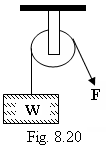
A. 11.52 N B. 18 N C. 57.6 N D. 288 N - Figure 8.23 shows a light, smooth pulley used to lift a load of 16 N with an effort E. The mechanical advantage of the system is
A. 128
B. 2
C. 1
D. 1/2 - Which one of the following is not a correct formula for calculating velocity ratio?
A. V.R = Distance moved by effort ÷ Distance moved by load
B. Effort × Distance moved by effort = Load × Distance moved by load
C. V.R = Load ÷ Effort
D. V.R = Number of teeth on driven gear ÷ Number of teeth on driving gear
SECTION B
- (a) What is meant by a first class lever?
(b) Give two examples of first class lever.
(c) By means of a lever, an effort of 50 N moves a load of 200 N through a distance of 3 m. If the effort moves a distance of 16 m, calculate:
(i) the mechanical advantage
(ii) the efficiency of the system. - (a) What is meant by efficiency of a machine?
(b) Draw a single string pulley system of velocity ratio 3.
(c) State one reason why the efficiency of a machine is always less than 100%. - (a) Define efficiency of a machine.
(b) The diagram in figure 8.24 above represents a pulley system in which an effort E is applied to raise the load L.
(i) Copy the diagram and indicate the forces acting on the string.
(ii) What is the velocity ratio of the system?
(iii) How far will the load move if the effort moves by 2.4 m?
(iv) What effort would just raise a load of 960 N, if the mechanical advantage is 2.4?
(v) Use your results above to calculate the efficiency of the pulley system.
(c) (i) Draw a sketch graph to show how the mechanical advantage of the pulley system in (b) varies with the load.
(ii) Explain the features of the sketch in (c) (i).
(d) Give two practical examples where pulley systems are used. - (a) Draw a labeled diagram to illustrate the lever principle as applied to a wheelbarrow.
(b) The graph in the figure shows the variation of the efficiency of a pulley system with load.
Explain why:
(i) part OA of the graph is almost a straight line.
(ii) from A, the graph curves and finally levels off before reaching 100%. - The figure 8.25 shows a wheel and axle system. When an effort of 300 N is applied, a load of 900 N is raised through a distance of 1.0 m.
Calculate:
(a) the velocity ratio
(b) the efficiency of the system - (a) State what is meant by each of the following terms as applied to simple machines:
(i) Mechanical advantage (ii) Efficiency
(b) (i) Give two reasons why the efficiency of any simple machine is always less than 100%.
(ii) Give two ways in which the efficiency of a machine can be increased.
(c) The figure shows a load of 10 N raised slowly by a simple frictionless pulley system.
(i) What is the velocity ratio of the system?
(ii) Calculate the effort required to lift the load if the mass of the pulley is 0.2 kg.
(iii) If the load is raised through a distance of 5 m in 5 s, calculate the efficiency of the system. - Two gear wheels A and B with 80 and 20 teeth respectively lock into each other. They are fastened on axles of equal diameters such that a weight of 150 N attached to a string wound around one axle raises a load of 450 N attached to a string wound around the other axle. Calculate:
(a) (i) the velocity ratio.
(ii) the efficiency of the system, if A drives B.
(b) (i) the velocity ratio.
(ii) the efficiency of the system, if B drives A. - A smooth wooden board 3.6 m long is used to raise a box of 600 N to a height of 1.2 m. Calculate:
(a) The effort required
(b) The M.A of the system.


