10. Floating-Point Representation
The simple fixed-point representation allows for a very limited range of values that can be represented. A more versatile scheme, the floating-point representation, overcomes this weakness. The radix point in this format is ‘floating’, as we adopt the concept of scientific notation. Some examples of values written in the scientific notation are shown below.

The scientific notation comprises the mantissa (also called significant), the base (or radix) and the exponent. Figure 5 shows the three components of a decimal number in scientific notation.

These representations: –12.3456 × 10³, –123456 × 10-1, and –0.00123456 × 10⁷ all represent the same value –12345.6. To achieve consistency and storage efficiency, we adopt a form where the mantissa is said to be normalized. A normalized mantissa is one in which the digit immediately after the radix point is non-zero. Therefore, the normalized form of our example would be –0.123456 × 10⁵.
The scientific notation is implemented as floating-point representation. The sign-and-magnitude format is usually chosen to represent the mantissa, and the base (radix) is assumed to be two, since numbers are represented in binary in computers. The floating-point format hence consists of three fields: a sign bit, a mantissa field, and an exponent field (the relative positions of the mantissa field and exponent field, as well as their widths, may vary from system to system), as shown in Figure 6.

The mantissa is usually normalized, so the first bit in the mantissa field must be a 1. Indeed, some systems further save on this bit, and store the mantissa only from the second bit onwards. The exponent field may be implemented in different schemes, such as sign-and-magnitude, 1’s complement, 2’s complement, or excess.
More bits for mantissa offers better precision, while a bigger exponent field provides a larger range of values. There is hence a trade-off between precision and range in determining the widths of these two fields.
The examples below assume a floating-point representation with 1-bit sign, 5-bit normalized mantissa, and 4-bit exponent for the value (0.1875)10, under the various schemes for exponent.

Multiplication on Floating-Point Numbers
The steps for multiplying two numbers A and B in floating-point representation are:
- Multiply the mantissas of A and B.
- Add the exponents of A and B.
- Normalize if necessary.
For example: if A = (0.11)2 × 24 and B = (0.101)2 × 2-1, then A × B = (0.11 × 0.101) × 24-1 = (0.01111)2 × 23 = (0.1111)2 × 22. This illustrates the multiplication of two decimal values 12 and 5/16 to obtain 3.75.
Addition on Floating-Point Numbers
The steps for adding two numbers A and B in floating-point representation are:
- Equalize the exponents of A and B.
- Add the mantissas of A and B.
- Normalize if necessary.
For example: if A = (0.11)2 × 24 and B = (0.101)2 × 2-1, then we convert A to (11000)2 × 2-1, so A + B = (11000 + 0.101) × 2-1 = (11000.101)2 × 2-1 = (0.11000101)2 × 24. This illustrates the addition of two decimal values 12 and 5/16 to obtain 12.3125.
IEEE Floating Point Representation
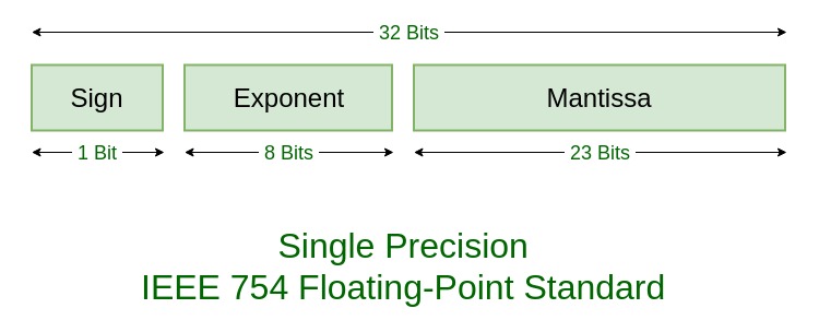
The IEEE has devised the IEEE Standard 754 floating point representation for representing real numbers on computers, adopted widely in Intel-based computers, Mackintoshes and most UNIX machines. It provides a 32-bit format for single-precision values, and a 64-bit format for double-precision values. The double-precision format contains a mantissa field that is more than twice as long as the mantissa field of the single-precision format, permitting greater accuracy.

The mantissa field assumes an implicit leading bit of 1, and the exponent field adopts the excess system with a bias value of 127 for the single-precision format, and a bias of 1023 for the double-precision format. Some representations are reserved for special values such as zero, infinity, NAN (not-a-number), denormalised values.
11. Codes
Our preceding discussion has been on the various representations for numeric values with the objective of easing arithmetic operations. However, we recognize that we are too accustomed to the decimal number system, whereas the ‘natural’ choice for computer representation is the binary number system, and the conversion between the two systems can be costly.
If arithmetic computations are not our concern, we may devise some coding schemes to represent decimal numbers. These schemes support quick conversion between the code and the value it represents, with the objective for data communications.
We shall discuss a few popular coding schemes such as BCD, Excess-3, 84-2-1, 2421, and the Binary codes. These codes are used to represent the ten decimal digits.
BCD (Binary Coded Decimal)
The BCD (Binary Coded Decimal) represents each decimal digit using a 4-bit code with weights 8, 4, 2 and 1. Hence it is also known as the 8421 code.
For example, the decimal number 294 would be represented as 0010 1001 0100 in BCD, with a 4-bit BCD code for each decimal digit in the number. (For negative values, the negative sign ‘–’ is to be coded separately and is not within the scope of BCD coding.)
Some codes are unused: 1010, 1011, …, 1111. These codes are considered as errors.
The BCD code offers the advantage of ease of conversion to its decimal equivalent. Performing arithmetic operations on BCD codes however, are more complicated and best avoided. BCD codes are useful for interfaces such as keypad inputs.
Excess-3 Code
The Excess-3 code uses a bias value of three. Hence the codes for the ten digits 0, 1, …, 9 are 0011, 0100, …, 1100 respectively. The decimal number 294 would be represented as 0101 1100 0111.
84-2-1 Code
The 84-2-1 code uses the weights of 8, 4, -2 and -1 in the coding. The decimal number 294 would be represented as 0110 1111 0100.
2421 Code
The 2421 code uses the weights of 2, 4, 2 and 1 in the coding. According to the weights, certain digits may have alternative codes. For instance, the digit 3 could be represented as 0011 or 1001. However, we pick the former in the standard 2421 coding, so that the codes for the first five digits 0 – 4 begin with 0, whereas the codes for the last five digits 5 – 9 begin with 1. The decimal number 294 would be represented as 0010 1111 0100.
Biquinary Code
The Biquinary code (bi=two, quinary=five) uses seven bits. The first two bits are either 01 (for representations of the first five digits) or 10 (for representations of the last five digits), and the following five bits consist of a single 1. The Biquinary code has error-detecting capability. The decimal number 294 would be represented as 0100100 1010000 0110000.
Comparison of Decimal Codes
BCD, Excess-3, 84-2-1, 2421 and Biquinary Codes
Table 7
| Decimal digit | BCD 8421 | Excess-3 | 84-2-1 | 2421 | Biquinary 5043210 |
|---|---|---|---|---|---|
| 0 | 0000 | 0011 | 0000 | 0000 | 0100001 |
| 1 | 0001 | 0100 | 0111 | 0001 | 0100010 |
| 2 | 0010 | 0101 | 0110 | 0010 | 0100100 |
| 3 | 0011 | 0110 | 0101 | 0011 | 0101000 |
| 4 | 0100 | 0111 | 0100 | 0100 | 0110000 |
| 5 | 0101 | 1000 | 1011 | 0101 | 1000001 |
| 6 | 0110 | 1001 | 1010 | 0110 | 1000010 |
| 7 | 0111 | 1010 | 1001 | 0111 | 1000100 |
| 8 | 1000 | 1011 | 1000 | 1000 | 1001000 |
| 9 | 1001 | 1100 | 1110 | 1111 | 1010000 |
Table 7 compares the common decimal codes. Note that the codes for the first five digits all begin with 0, while the codes for the last five digits begin with 1. Other codes exist, such as the 5211 code.
The following are some definitions:
- A weighted code is one where each bit position has an associated weight. The BCD, 84-2-1, 2421 and Biquinary codes are all weighted codes.
- A self-complementing (or reflective) code is one in which the codes for complementary digits are also complementary to each other. For instance, the Excess-3 code for digit 2 is 0101, while the code for digit 7 (the complement of 2) is 1010 (the complement of 0101). The Excess-3, 84-2-1 and 2421 codes are self-complementing.
- A sequential code is one in which each succeeding code value is one binary value greater than its preceding code value. The BCD and Excess-3 codes are sequential.
ASCII Code
Apart from numerical values, computing devices also handle textual data comprising characters. The character set includes letters in the alphabet (‘A’ … ‘Z’, ‘a’ … ‘z’), digits (‘0’ … ‘9’), special symbols (‘+’, ‘$’, ‘.’, ‘;’, ‘@’, ‘*’, etc.) and non-printable characters (control-A, backspace, control-G, etc.).
The ASCII (American Standard Code for Information Interchange) character set is a commonly used standardized code that uses 7 bits, plus a parity bit for error detection. Table 8 shows the ASCII character set. Every character has a unique ASCII value. The ASCII value of character ‘A’, for example, is (1000001)2 or (65)10.
The ASCII Character Set
Table 8
| MSBs | ||||||||
| LSBs | 000 | 001 | 010 | 011 | 100 | 101 | 110 | 111 |
| 0000 | NUL | DLE | SP | 0 | @ | P | ` | p |
| 0001 | SOH | DC1 | ! | 1 | A | Q | a | q |
| 0010 | STX | DC2 | “ | 2 | B | R | b | r |
| 0011 | ETX | DC3 | # | 3 | C | S | c | s |
| 0100 | EOT | DC4 | $ | 4 | D | T | d | t |
| 0101 | ENQ | NAK | % | 5 | E | U | e | u |
| 0110 | ACK | SYN | & | 6 | F | V | f | v |
| 0111 | BEL | ETB | ‘ | 7 | G | W | g | w |
| 1000 | BS | CAN | ( | 8 | H | X | h | x |
| 1001 | HT | EM | ) | 9 | I | Y | i | y |
| 1010 | LF | SUB | * | : | J | Z | j | z |
| 1011 | VT | ESC | + | K | [ | k | { | |
| 1100 | FF | FS | , | < | L | l | | | |
| 1101 | CR | GS | – | = | M | ] | m | } |
| 1110 | O | RS | . | > | N | ^ | n | ~ |
| 1111 | SI | US | / | ? | O | _ | o | DEL |
Parity Bit
Errors may occur during data transmission. If we could detect the error, we could request for re-transmission. Better still, if the error could be corrected automatically, it would save the re-transmission, but this requires a more complex mechanism.
The Biquinary code uses 7 bits, 3 more bits than the usual 4-bit codes such as BCD, to provide error-detection capability. If a supposedly Biquinary code received shows 0101001, we detect the error instantly.
For the detection of single-bit error – a bit is inverted during the transmission – a simple error-detection scheme called the parity bit scheme can be used. An additional parity bit is attached (usually appended) to the data. The parity bit scheme comes in two flavours: the odd parity and the even parity.
In the odd parity scheme, the additional parity bit is chosen so that the total number of 1’s in the data, including the parity bit, is an odd number. Likewise, for even parity scheme, the total number of 1’s in the data and parity must be even.
If we use the odd parity scheme on the ASCII character set, then the character ‘A’, having the ASCII value 1000001, would be appended with the parity bit 1 to become 10000011.
The parity bit scheme detects only single-bit error. If two bits are inverted during data transmission, it would go undetected under this scheme.
The parity bit scheme may be extended to a block of data. For example, in Figure 8, a block of five 4-bit words is shown on the left. On the right, it is shown how a parity bit is appended to each of the five words, and an additional parity word is added where each bit in that parity word is the parity bit for its associated column. Odd parity scheme is assumed in this example.

The parity bit scheme has limited ability on error correction. More complex schemes, such as the Hamming code, are needed to do error correction.
12 Gray Code
We shall conclude this chapter with a special code – the Gray code. The Gray code is neither a decimal code, nor is it an arithmetic code created for the purpose of computation.
The essential feature of a Gray code is that there is only a single bit change from one code value to the next. The sequence is circular. This feature makes the Gray code suitable for error detection applications.
With the above feature in mind, the following two sequences are examples of 2-bit Gray codes:
Sequence #1: 00 → 01 → 11 → 10 → (back to 00)
Sequence #2: 00 → 10 → 11 → 01 → (back to 00)
Other sequences can be derived from the above two sequences, by choosing one of the code values as the first code value in the cyclic sequence. Among all the valid Gray code sequences, we adopt the first sequence above as the standard 2-bit Gray code sequence.
Table 9 shows the standard 4-bit Gray code sequence. The binary sequence is shown alongside the Gray code sequence for comparison.

Binary-to-Gray Conversion
The algorithm to convert a binary value to its corresponding standard Gray code value is as follows:
- Retain the MSB.
- From left to right, add each adjacent pair of binary code bits to get the next Gray code bit, discarding the carry.
The following example shows the conversion of binary number (10110)2 to its corresponding standard Gray code value, (11101)Gray.

Gray-to-Binary Conversion
The algorithm to convert a standard Gray code value to its corresponding binary value is as follows:
- Retain the MSB.
- From left to right, add each binary code bit generated to the Gray code bit in the next position, discarding the carry.
The following example shows the conversion of the standard Gray code value (11011)Gray to its corresponding binary value, (10010)2.

Let us consider a disk whose surface is divided into eight sectors. Each sector is identified by a 3-bit code. Figure 9a shows the binary coding on the sectors, and Figure 9b the Gray coding.

With misaligned sensors, on a disk with binary coded sectors, Figure 9c shows an instance where the system registers the transition from sector 001 to 000 to 010 as the disk rotates, where in fact the correct transition should be sector 001 to 010. The spurious sector 000 registered is due to the binary coded sequence, as one of the misaligned sectors crosses into the next sector before the other sensors. Figure 9d shows that a Gray coded sequence would eliminate such error.
Quick Review Questions
2-1. Convert the binary number 1011011 to its decimal equivalent.
a. 5 b. 63 c. 91 d. 92 e. 139
2-2. What is the weight of the digit ‘3’ in the base-7 number 12345?
a. 3 b. 7 c. 14 d. 21 e. 49
2-3. Which of the following has the largest value?
a. (110)10 b. (10011011)2 c. (1111)5 d. (9A)16 e. (222)8
2-4. If (321)4 = (57)10, what is the decimal equivalent of (321000000)4?
a. 57 × 104 b. 57 × 106 c. 57 × 44 d. 57 × 46 e. 574
2-5. Convert each of the following decimal numbers to binary (base two) with at most eight digits in the fractional part, rounded to eight places.
a. 2000 b. 0.875 c. 0.07 d. 12.345
2-6. Convert each of the decimal numbers in Question 2-5 above to septimal (base seven) with at most six digits in the fractional part, rounded to six places.
2-7. Convert each of the decimal numbers in Question 2-5 above to octal (base eight) with at most four digits in the fractional part, rounded to four places.
2-8. Convert each of the decimal numbers in Question 2-5 above to hexadecimal (base sixteen) with at most two digits in the fractional part, rounded to two places.
2-9. Which of the following octal values is equivalent to the binary number (110001)2?
a. (15)8 b. (31)8 c. (33)8 d. (49)8 e. (61)8
2-10. Convert the binary number (1001101)2 to
a. quaternary b. octal c. decimal d. hexadecimal
2-11. What is (1011)2 × (101)2?
a. (10000)2 b. (110111)2 c. (111111)2 d. (111011)2 e. (101101)2
2-12. Perform the following operations on binary numbers.
a. (10111110)2 + (10001101)2
b. (11010010)2 – (01101101)2
c. (11100101)2 – (00101110)2
2-13. In a 6-bit 2’s complement binary number system, what is the decimal value represented by (100100)2s?
a. –4 b. 36 c. –36 d. –27 e. –28
2-14. In a 6-bit 1’s complement binary number system, what is the decimal value represented by (010100)1s?
a. –11 b. 43 c. –43 d. 20 e. –20
2-15. What is the range of values that can be represented in a 5-bit 2’s complement binary system?
a. 0 to 31 b. –8 to 7 c. –8 to 8 d. –15 to 15 e. –16 to 15
2-16. In a 4-bit 2’s complement scheme, what is the result of this operation: (1011)2s + (1001)2s?
a. 4 b. 5 c. 20 d. –12 e. overflow
2-17. Assuming a 6-bit 2’s complement system, perform the following subtraction operations by converting it into addition operations:
a. (011010)2s – (010000)2s
b. (011010)2s – (001101)2s
c. (000011)2s – (010000)2s
2-18. Assuming a 6-bit 1’s complement system, perform the following subtraction operations by converting it into addition operations:
a. (011111)1s – (010101)1s
b. (001010)1s – (101101)1s
c. (100000)1s – (010011)1s
2-19. Which of the following values cannot be represented accurately in the 8-bit sign-and-magnitude fixed-point number format shown in Figure 2.4?
a. 4 b. –29.5 c. 20.2 d. –3.75 e. 12.25
2-20. What does 1 110 1001 represent in this floating-point number scheme: 1-bit sign, 3-bit normalized mantissa, followed by 4-bit 2’s complement exponent?
a. 0.125 × 29 b. –0.125 × 29 c. –0.75 × 2-1 d. –0.75 × 2-6 e. –0.75 × 2-7
2-21. How to represent (246)10 in the following system/code?
a. 10-bit binary b. BCD c. Excess-3 d. 2421 code e. 84-2-1 code
2-22. The decimal number 573 is represented as 1111 0110 1011 in an unknown self-complementing code. Find the code for the decimal number 642.
2-23. Convert (101011)2 to its corresponding Gray code value.
a. (101011)Gray b. (010100)Gray c. (110010)Gray d. (111110)Gray e. (43)Gray
2-24. Convert (101011)Gray to its corresponding binary value.
a. (101011)2 b. (010100)2 c. (110010)2 d. (111110)2 e. (010101)2
Answers to Quick Review Questions
2-1. (c) 2-2. (e) 2-3. (c) 2-4. (d)
2-5. (a) (2000)10 = (11111010000)2 (b) (0.875)10 = (0.111)2
(c) (0.07)10 = (0.00010010)2 (d) (12.345)10 = (1100.01011000)2
2-6. (a) (2000)10 = (5555)7 (b) (0.875)10 = (0.606061)7
(c) (0.07)10 = (0.033003)7 or (0.033004)7
(d) (12.345)10 = (15.226223)7
2-7. (a) (2000)10 = (3720)8 (b) (0.875)10 = (0.7)8
(c) (0.07)10 = (0.0437)8
(d) (12.345)10 = (14.2605)8
2-8. (a) (2000)10 = (7D0)16 (b) (0.875)10 = (0.E)16
(c) (0.07)10 = (0.12)16
(d) (12.345)10 = (C.58)16
2-9. (e)
2-10. (a) (1031)4 (b) (115)8 (c) (77)10 (d) (4D)16
2-11. (b)
2-12. (a) (101001011)2 (b) (01100101)2 (c) (10110111)2
2-13. (e) 2-14. (d) 2-15. (e) 2-16. (e)
2-17. (a) (001010)2s = (10)10 (b) (001101)2s = (13)10 (c) (110011)2s = –(13)10
2-18. (a) (001010)1s = (10)10 (b) (011100)1s = (28)10 (c) overflow
2-19. (c) 2-20. (e)
2-21. (a) (0011110110)2 (b) (0010 0100 0110)BCD (c) (0101 0111 1001)Excess-3
(d) (0010 0100 1100)2421 (e) (0110 0100 1010)84-2-1
2-22. 642 = 0100 0000 1001
2-23. (d) 2-24. (c)
Exercises
2-25. How is subtraction carried out for binary numbers represented in the sign-and-magnitude form?
2-26. According to the fixed-point number format in Figure 2.4, what are the largest and smallest positive values that can be represented? What are the largest and smallest negative values?
2-27. Find out how the special values are represented in the IEEE Standard 754 floating-point representation.
2-28. Perform the following number system conversions:
(a) 11010112 = ?
(b) 67.248 = ?2
(c) DEAD.BEEF16 = ?8
(d) 10100.11012 = ?10
(e) 71568 = ?10
(f) 15C.3816 = ?10
(g) 12510 = ?2
(h) 143510 = ?8
2-29. Sometimes we need to round a value to a specified number of places. Perform the following rounding, providing an answer that is most accurate.
(a) The answer for question 2-28b, correct to two places.
(b) The answer for question 2-28b, correct to one place.
(c) The answer for question 2-28c, correct to three places.
(d) The answer for question 2-28c, correct to two places.
2-30. Add the following pairs of unsigned binary numbers (unsigned numbers are non-negative values), showing all carries:

2-31. Write the 8-bit sign-and-magnitude, 1’s-complement, and 2’s-complement representations for each of these decimal numbers:
+18, +115, +79, –49, –3, –100.
2-32. The diminished radix complement of base-6 numbers is called the 5’s complement.
(a) Obtain the 5’s complement of (543210)6.
(b) Design a 3-bit self-complementing code to represent each of the six digits of the base-6 number system.
2-33. Convert the following binary numbers into standard Gray codes:
(a) 010112 (b) 1011012 (c) 101011112
2-34. Convert the following standard Gray codes into binary numbers:
(a) 01011Gray (b) 101101Gray (c) 10101111Gray
2-35. Represent the decimal 3951 in the following coding schemes:
(a) BCD code
(b) Excess-3 code
(c) 2421 code
(d) 84-2-1 code
(e) ASCII (ASCII code for character ‘0’ is 4810, or 01100002.)
2-36. Complete the following sequence so that the result is a 3-bit Gray code sequence.
011 → ? → ? → 100 → 101 → 001 → ? → ?
Boolean Algebra Logic and Logic Gates
Basic Theorems and Properties of Boolean Algebra:
Duality
We simply interchange OR and AND operators and replace 1’s by 0’s and 0’s by 1’s. Also, the duality principle states that if two Boolean expressions are equal, then their duals are also equal. Ex: X + 0 = X and X · 1 = X.
Basic Theorem
Boolean Addition:
x + 0 = 0 + x = x (0 is called the additive identity)
x + 1 = 1 (x + 1 = 1)
Boolean Multiplication:
x · 0 = 0
x · 1 = 1 · x = x (1 is called the multiplicative identity)
Idempotent Laws
x + x = x
x x = x
Involution Law
(x’)’ = x
Laws of Complement
x + x’ = 1
x · x’ = 0
Commutative Laws
x + y = y + x
x y = y x
Associative Laws
(x + y) + z = x + (y + z) = x + y + z
(x · y) · z = x (y · z) = x · y · z
Distributive Law
x · (y + z) = (x · y) + (x · z)
x + (y · z) = (x + y) · (x + z)
De Morgan’s Laws
(x + y)’ = x’ y’
(x · y)’ = x’ + y’
Consensus Law
x · y + x’ · z + y · z = x · y + x’ · z
The term yz is referred to as the “consensus term”. A consensus term is a redundant term and it can be eliminated. Given a pair of terms for which a variable appears in one term and the complement of that variable in another term, the consensus term is formed by multiplying the two original terms together, leaving out the selected variables and its complement.
Field
A field is a set of elements, together with two binary operators.
The set of real numbers together with the binary operators + and · form the field of real numbers.
The field of real numbers is the basis for arithmetic and ordinary algebra. The operators and postulates have the following meanings:
- The binary operator + defines addition.
- The additive identity is 0.
- The additive inverse defines subtraction.
- The binary operator · defines multiplication.
- The multiplicative identity is 1.
- The multiplicative inverse of a = 1/a defines division, i.e. a · 1/a = 1.
- The only distributive law applicable is that of · over +:
a · (b + c) = (a · b) + (a · c)
A two-valued Boolean Algebra
is defined on a set of 2 elements, B = {0, 1}, with rules for the 2 binary operators + and ·.


Logic Gates

Operator Precedence
The operator precedence for evaluating Boolean expressions is (1) (), (2) NOT, (3) AND, and (4) OR. Ex: (x + y)’.
Venn Diagram
See Fig. 2–1, 2–2 Page 44.
Boolean Functions
A Boolean function is an expression formed with binary variables, the two binary operators OR and AND, and unary operator NOT, parentheses, and an equal sign. For a given value of the variables, the function can be either 0 or 1.
Ex: F1 = xyz’. The function is equal to 1 if x = 1 and y = 1 and z’ = 1; otherwise F1 = 0.
To represent a function in a truth table, we list 2n combinations of 1’s and 0’s of n binary variables and a column to show the combination for which the function = 0, 1.
Truth tables for F1 = xyz’, F2 = x + y’z, F3 = x’y’z + x’yz + xy’, and F4 = xy’ + x’z

Two functions of n binary values are said to be equal if they have the same value for all possible 2n combinations of the n variables. F3 and F4 are equal Boolean functions.
A Boolean function may be transformed from an algebraic expression into a logic diagram composed of AND, OR, and NOT gates. Fig. 4.
Since F3 and F4 are equal Boolean functions, it is more economical to implement the F4 form than the F3 form.
Algebraic Manipulation
A literal is a primed or unprimed variable. When a Boolean function is implemented with logic gates, each literal in the function designates an input to a gate, and each term is implemented with a gate.
The number of literals in a Boolean function can be minimized by algebraic manipulations.
There are no specific rules to follow that will guarantee the final answer.
The only method available is a cut-and-try procedure employing postulates, basic theorems, and other manipulation methods that become familiar with use.
Ex:
Simplify the following Boolean functions to a minimum number of literals.
- x + x’y = (x + x’)(x + y) = 1(x + y) = x + y
- x(x’ + y) = (x x’) + (x y) = 0 + xy = xy
- x’y’z + x’yz + xy’ = x’z(y + y’) + xy’ = x’z + xy’
- xy + x’z + yz = xy + x’z + yz(x + x’)
= xy + x’z + xyz + x’yz
= xy(1 + z) + x’z(1 + y)
= xy + x’z
Functions 1 and 2 are the duals of each other and use dual expressions in corresponding steps.
Complement of a function
The complement of a function F is F’ and is obtained from an interchange of 0’s for 1’s and 1’s for 0’s in the values of F.
The complement of a function may be derived algebraically through De Morgan’s:
(A + B + C + D + … + F)’ = A’ B’ C’ D’ … F’
(A B C D … F)’ = A’ + B’ + C’ + D’ + … + F’
The generalized form of De Morgan’s theorem states that the complement of a function is obtained by interchanging AND and OR operators and complementing each literal.
F1 = x’y z’ + x’y’ z
F’1 = (x + y’ + z)(x + y + z’)
F2 = x(y’ z’ + y z)
F’2 = x’ + (y + z)(y’ + z’)
Representations of A Function
A function can be specified or represented in any of the following ways:
- A truth table
- A circuit
- A Boolean expression
- SOP (Sum Of Products)
- POS (Product of Sums)
- Canonical SOP
- Canonical POS
Canonical And Standard Forms
Min terms and Max terms
A binary variable may appear in normal form (x) or in complement form (x’).
Ex: Two binary variables x and y combined with an AND gate. There are four combinations: x’y’, x’y, xy’, & xy.
Each of these four AND terms represents one of the distinct areas in the Venn diagram and is called a min term or a standard product.
Similarly, n variables can be combined to form 2n min terms. The 2n different min terms may be determined by a method similar to the table shown below.
Each min term is obtained from an AND term of the n variables, with each variable being primed if the corresponding bit of the binary number is a 0 and unprimed if a 1.
In a similar fashion, n variables can be combined to form 2n max terms or standard sums. The 2n different max terms may be determined by a method similar to the table shown below.
Each max term is obtained from an OR term of the n variables, with each variable being primed if the corresponding bit of the binary number is a 1 and unprimed if a 0.
Each max-term is the complement of its corresponding min term, and vice versa.
A Boolean function may be expressed algebraically from a given truth table by forming a min term for each combination of the variables that produces a 1 in the function and then taking the OR of those terms.

Ex: the function in the following table is determined by expressing the combination of 001, 100, and 111 as x’y’z, xy’z’, and xyz. Since each one of these minterms results in f1 = 1, we should have
f1 = x’y’z + xy’z’ + xyz = m1 + m4 + m5 + m6 + m7
Similarly, we can verify that
f2 = x’yz + xy’z + xyz’ + xyz = m2 + m3 + m5 + m6 + m7
The complement of f1 is “may be read from the truth table by forming a min term for each combination that produces a 0 in the function and then ORing those terms”:
f’1 = x’y’z’ + x’yz’ + x’yz + xy’z + xyz’
Functions of Three Variables

If we take the complement of f’1, we obtain the function f1:
f1 = (x + y + z)(x + y’ + z)(x + y’ + z’)(x’ + y + z’)(x’ + y’ + z)
= M0 · M2 · M3 · M5 · M6
Similarly, it is possible to read the expression for f2 from the table:
f2 = (x + y + z)(x + y + z’)(x + y’ + z)(x’ + y + z’)(x’ + y + z)
= M0 · M1 · M2 · M4
Boolean functions expressed as a sum of min terms or products of max terms are said to be in canonical form.
Sum of Min terms

F (A, B, C) = Σ (1, 4, 5, 6, 7)
Ex: Express the function F = A + B’C in a sum of min terms. The function has 2 variables.
Term A is missing 2 variables:
A = A (B + B’) = AB + AB’. Now A is missing 1 variable
A = AB (C + C’) + AB’ (C + C’)
A = ABC + ABC’ + AB’C + AB’C’
B’C is missing one variable:
B’C = B’C (A + A’) = AB’C + A’B’C. Now we combine terms
F = ABC + ABC’ + AB’C’ + AB’C + A’B’C
= m1 + m4 + m5 + m6 + m7
Product of Max terms
Truth Table for F = xy + x’z

The sum of min terms is
F (x, y, z) = Σ (1, 3, 6, 7)
The sum of max terms is
F (x, y, z) = ∏(0, 2, 4, 5)
Ex: Express the Boolean function F = xy + x’z in a product of max terms. Convert the function into OR terms using the distributive law:
F = xy + x’y = (xy + x’) (xy + z)
= (x + x’) (y + x’) (x + z) (y + z)
= (x’ + y) (x + z) (y + z)
The function has 3 variables: x, y, & z. Each OR term is missing one variable:
x’ + y = x’ + y + zz’ = (x’ + y + z) (x’ + y + z’)
x + z = x + z + yy’ = (x + y + z) (x + y’ + z)
y + z = y + z + xx’ = (x + y + z) (x’ + y + z’)
Combine the terms and remove the terms that appear more than once:
F = (x + y + z) (x + y’ + z) (x’ + y + z) (x’ + y + z’)
= M0 + M2 + M4 + M5
The function is expressed as follows: F (x, y, z) = ∏ (0, 2, 4, 5)
Conversion between Canonical Forms
Ex: The complement of
F (A, B, C) = Σ (1, 4, 5, 6, 7) is
F’ (A, B, C) = Σ (0, 2, 3) = m0 + m2 + m3
If we apply the complement of F’ using De Morgan’s theorem, we obtain F in a different form:
F = (m0 + m2 + m3)’ = m’0 · m’2 · m’3 = ∏ (0, 2, 3)
The last conversion follows from the definition of min terms and max terms. It is clear that the following relation holds true: m’j = Mj, the max term with subscript j is a complement of the min term with the same subscript j, and vice versa.
To convert from one canonical form to another, interchange the symbol Σ and ∏ and list those numbers missing from the original form.
Integrated Circuits “IC”
It’s a small silicon semiconductor, called a chip, containing the electronic components for the digital gates. The gates are interconnected inside the chip to form the required circuit.
Levels of Integration
- Small-scale Integration (SSI): contains several independent gates in a single package. The number of gates is usually fewer than 10.
- Medium-scale Integration (MSI): have a complexity between 10 and 100 gates in a single package. They perform specific digital operations such as decoders, adders, and multiplexers.
- Large-scale Integration (LSI): contains between 100 and 1000s gates in a single package. They include processors, memory chips, and programmable logic devices.
- Very Large-scale Integration (VLSI): contains thousands of gates in a single package. Examples are large memory arrays and complex microcomputer chips.